Description
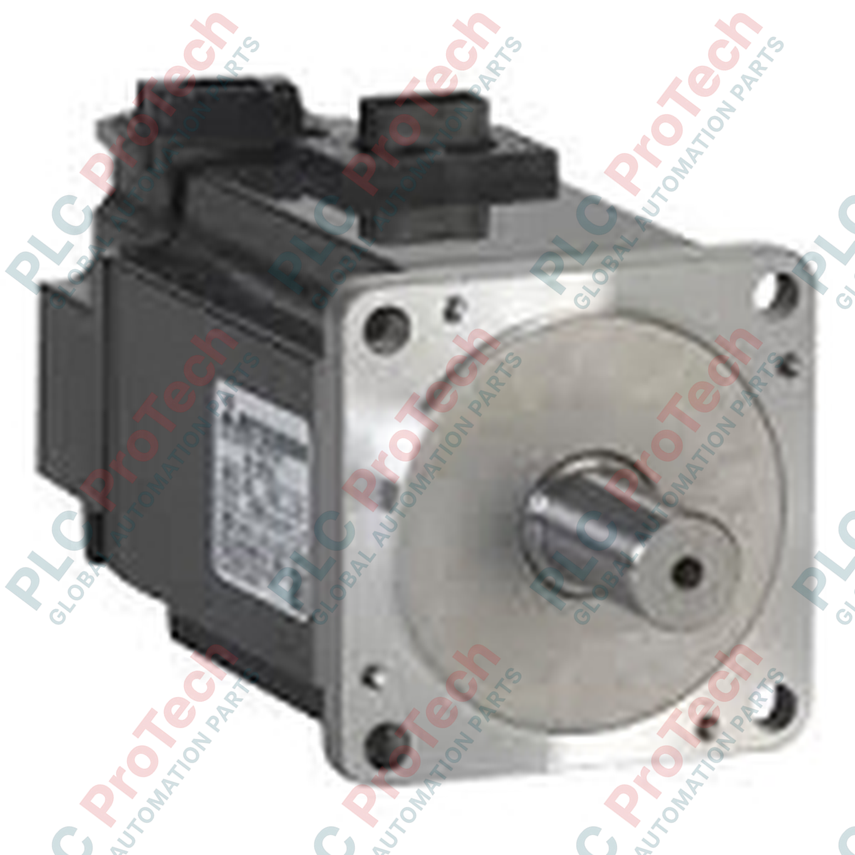
Optimized for high-duty cycle industrial automation systems, the Mitsubishi Electric HC-SFS502 is a high-performance AC servo motor designed to deliver precise torque and speed control within the medium-inertia, medium-capacity HC-SFS Series. Rated at 5.0 kW with a nominal speed of 2000 r/min, this industrial motor provides the mechanical stiffness and dynamic response required for heavy-duty positioning tasks. It is engineered to pair natively with the MR-J2S-500A and MR-J2S-500B servo amplifiers, ensuring seamless integration into the MELSEC control architecture and maintaining high-speed communication stability under demanding operating conditions.
Features
-
Medium Inertia Design: Highly suited for applications with fluctuating load inertias, offering stable tuning and reduced mechanical resonance.
-
High Torque Density: Delivers a rated output of 5.0 kW in a compact form factor, optimizing cabinet and machine footprint.
-
IP65 Protection Rating: Fully sealed against dust ingress and low-pressure water jets (excluding the shaft opening), ensuring reliable operation in harsh manufacturing environments.
-
Integrated Encoder Feedback: Equipped with a high-resolution absolute/incremental encoder for precise closed-loop positioning accuracy.
Applications
- Automotive assembly line gantries and transfer systems.
- High-speed packaging and material handling machinery.
- Metal stamping, forming, and CNC auxiliary axes.
- Large-scale printing presses and tension control systems.
Technical Specifications
| Parameter |
Value / Specification |
| Manufacturer |
Mitsubishi Electric |
| Model Number |
HC-SFS502 |
| Series Name |
HC-SFS Series (Medium Inertia / Medium Capacity) |
| Rated Output Power |
5.0 kW |
| Rated Speed |
2000 r/min |
| Maximum Speed |
3000 r/min |
| Power Facility Capacity |
7.5 kVA |
| Compatible Servo Amplifier |
MR-J2S-500A / MR-J2S-500B |
| IP Rating |
IP65 (excluding shaft axis) |
| Ambient Operating Temperature |
0 to 40 degC |
| Shipping Weight (Calculated) |
30.0 kg |
| Package Dimensions (Calculated) |
480 mm x 320 mm x 320 mm |
Empirical Engineering Insights
Alternative Models & Compatibility
The HC-SFS502 is part of the legacy MR-J2S platform. When upgrading systems or sourcing spares, note that this motor cannot be run directly by newer MR-J3 or MR-J4 amplifiers without specific legacy emulation parameters or drive-matching modules. If transitioning to the newer HG-SR series (e.g., HG-SR502), mount geometry and connector pinouts differ; physical adapter plates and custom cable assemblies are required to adapt the legacy footprint.
Application Pitfalls & Engineering Notes
Due to the 5.0 kW power draw, regeneration energy is a critical consideration during rapid deceleration. Always calculate the thermal capacity of your external regenerative resistors connected to the MR-J2S-500A/B drive. Underestimating deceleration duty cycles can lead to overvoltage trips (Alarm 10 or Alarm 33) on the amplifier. Ensure adequate cooling clearances around the motor body, as medium-inertia motors operating in continuous-duty applications require unobstructed ambient airflow to prevent thermal runaway.
Commissioning & Wiring Tips
Always use original Mitsubishi high-flex encoder and power cables to avoid high-frequency noise interference, which can cause feedback loss (Alarm 16 or Alarm 20). Ensure that the encoder cable shield is grounded directly to the amplifier’s chassis plate. When tuning the MR-J2S amplifier, set the initial load inertia ratio manually before running auto-tuning, as the high-inertia characteristics of the HC-SFS502 can cause standard auto-tuning loops to overshoot, resulting in physical machine vibration.
Installation Guidelines
CRITICAL WARNING: HIGH VOLTAGE & RESIDUAL CHARGE
Before executing any installation, maintenance, or wiring procedures, isolate the main 3-phase AC power feeding the servo amplifier. Wait at least 20 minutes for the internal DC bus capacitors of the MR-J2S-500 amplifier to discharge fully. Verify zero-voltage state across the L+ and L- terminals with a calibrated digital multimeter before handling connections.
1
Mechanical Mounting: Secure the motor to a rigid machine frame using heavy-duty, high-tensile mounting bolts. Misalignment of the motor shaft and the driven load must be minimized to prevent premature bearing wear and shaft fracture.
2
Shaft Preparation: Apply a thin coat of anti-seize lubricant to the motor shaft. When installing pulleys or couplings, do not apply axial or radial impact forces (e.g., hitting with a hammer), as this can damage the internal high-resolution optical encoder disk.
3
Power & Feedback Connections: Securely plug in the heavy-duty power connector and encoder feedback cables. Ensure the cable strain reliefs are properly clamped so that no tension is transferred directly to the motor's internal connector housing.