Description
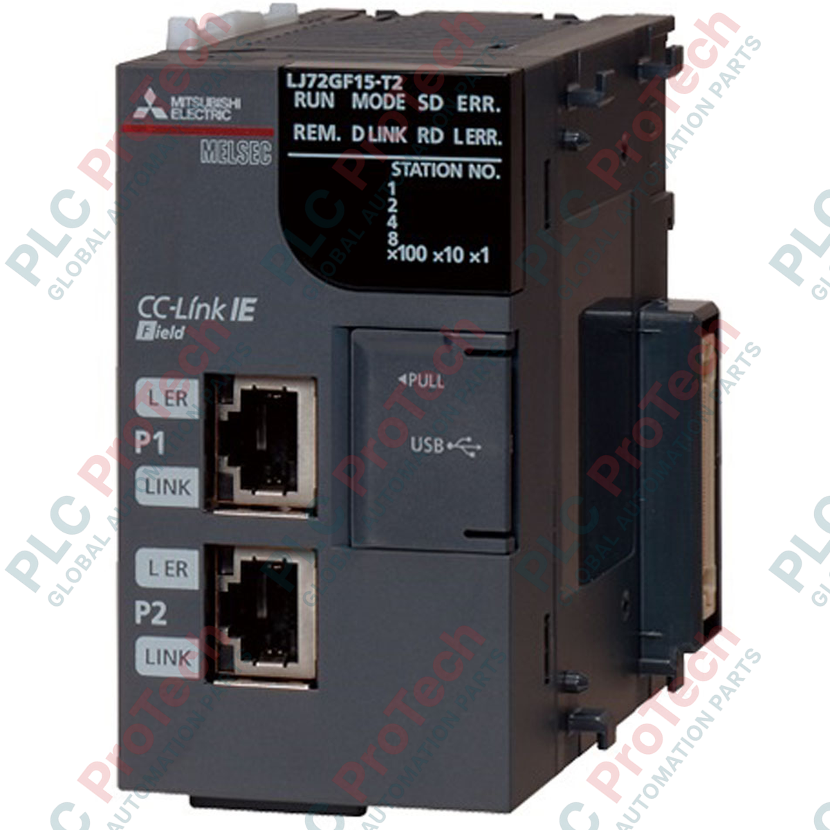
Establishing reliable, deterministic remote node connectivity within distributed automation architectures, the Mitsubishi Electric LJ72GF15-T2-CM operates as a high-performance CC-Link IE Field Network Head Module. This intelligent device station links decentralized digital and analog I/O modules directly to a master controller over a high-speed Ethernet backbone. Engineered for the MELSEC L Series platform, it supports complex modular topologies while maintaining rapid response times and extensive diagnostics across the industrial network.
Features
-
High-Speed Transmission: Supports 1 Gbps communication speeds over standard industrial Ethernet media for near-zero latency cyclic data exchange.
-
Extensive Node Capacity: Manages up to 2048 remote I/O points and 1024 words of remote register data per station.
-
Integrated RAS Functions: Features built-in Reliability, Availability, and Serviceability diagnostics to pinpoint network faults instantly.
-
System Completeness: Supplied standard with the required END bus cover to ensure correct backplane termination.
-
Modular Expandability: Allows direct attachment of standard MELSEC L Series digital, analog, and specialty function modules.
Applications
- Automotive assembly lines requiring high-speed distributed I/O control.
- Packaging and material handling systems with remote conveyor nodes.
- Water treatment facilities utilizing scattered instrumentation stations.
- Multi-zone thermal control processes and remote telemetry panels.
Technical Specifications
| Parameter |
Specification |
| Manufacturer |
Mitsubishi Electric |
| Model Number |
LJ72GF15-T2-CM |
| Product Series |
MELSEC L Series |
| Station Type |
CC-Link IE Field Intelligent Device Station |
| Communication Speed |
1 Gbps |
| Max. Remote I/O Points |
2048 points |
| Max. Remote Register Capacity |
1024 words |
| Internal Current Consumption (5V DC) |
1.00 A |
| RAS Functions |
Supported (Hardware diagnostics, loopback tests, link status tracking) |
| Included Accessories |
END cover termination unit |
| Net Weight |
0.23 kg |
| Shipping Weight (Calculated) |
2.00 kg |
Connections and Interfaces
| Interface Port |
Connection & Cable Type |
Function Description |
| PORT 1 / PORT 2 |
RJ45 Connector (Cat5e or higher STP, double-shielded) |
CC-Link IE Field Network Line connection (supports line, star, and ring topologies) |
| Station No. Switches |
Rotary hardware switches (x1, x10) |
Manual network station address configuration (1 to 120) |
Empirical Engineering Insights
Alternative Models & Compatibility
The "-CM" suffix indicates compliance and localized packaging standards, but functionally mirrors the standard LJ72GF15-T2. It is fully cross-compatible with standard MELSEC L Series power supply modules, digital I/O, and analog modules. Ensure your engineering environment is updated with the correct CSP+ profiles in GX Works2 or GX Works3 to correctly discover the device station during network configuration.
Application Pitfalls & Engineering Notes
A common field failure involves network dropouts caused by electromagnetic interference (EMI). Because CC-Link IE Field operates at 1 Gbps, standard unshielded Cat5 cable is highly susceptible to variable frequency drive (VFD) noise. Double-shielded (STP) Category 5e or Category 6 cables with grounded metal RJ45 shells must be used. Additionally, compute the total 5V DC backplane current consumption: if adding high-density modules exceeds the power supply module's capacity, the head module will shut down or experience intermittent communications.
Commissioning & Wiring Tips
The head module will fail to boot and display a hardware bus error if the physical END cover is not securely locked onto the rightmost slot of the overall assembly. Always perform a physical latch-check before powering up. When setting the station number using the rotary dials, make sure to cycle the main system power; the module only reads the rotary switch state during the initial hardware initialization phase.
Installation Guidelines
CRITICAL WARNING: Before installing, removing, or wiring any module in the assembly, ensure the main external power source is completely disconnected on all phases. Failure to do so can result in electrical shock, backplane bus damage, or immediate hardware failure.
1
Mount the head module onto the DIN rail, ensuring the unit's DIN rail hooks are securely engaged and locked.
2
Align the side joint connectors of the adjacent power supply and I/O modules, sliding them together until they click into place, then engage the module joint levers.
3
Affix the supplied END cover onto the rightmost module slot of the completed rack assembly.
4
Set the station number on the front-panel rotary switches using a small precision screwdriver, and connect the double-shielded Ethernet cables to PORT 1 or PORT 2.