Description
Precision motion profiles in demanding industrial automation architectures are governed by the Mitsubishi Electric MR-J3-500A, a digital MELSERVO-J3 AC Servo Amplifier designed to drive 5.0 kW rotary servo motors. This unit features a versatile general-purpose analog and pulse-train interface, enabling seamless integration into conventional positioning, velocity, and torque control loops. By leveraging real-time adaptive auto-tuning and advanced vibration suppression filters, this amplifier dynamically counteracts mechanical resonance and load inertia fluctuations, ensuring stable, high-speed positioning operations.
Features
-
High-Resolution Feedback Compatibility: Interfaces natively with 18-bit absolute/incremental encoders (262,144 pulses per revolution) to ensure exceptional speed stability and tracking precision.
-
Advanced Vibration Suppression: Employs adaptive vibration control filters that automatically adjust to eliminate high-frequency mechanical resonances and low-frequency load oscillations.
-
Real-Time Auto-Tuning: Continuously monitors machine inertia changes during operation, automatically optimizing gain parameters without requiring manual site intervention.
-
Rugged Electrical Design: Includes built-in dynamic braking circuits for controlled emergency deceleration under high-inertia conditions.
Applications
- High-speed pick-and-place packaging systems.
- Multi-axis CNC machining centers and metal forming machinery.
- Automated materials handling and high-capacity gantry lifters.
- Automotive assembly lines and precision indexing tables.
Technical Specifications
| Parameter |
Specification Value |
| Manufacturer |
Mitsubishi Electric |
| Model Number |
MR-J3-500A |
| Series |
MELSERVO-J3 |
| Compatible Motor Capacity |
5.0 kW (5000 W) |
| Main Circuit Power Input |
3-phase 200 to 230 VAC, 50/60 Hz |
| Control Circuit Power Input |
Single-phase 200 to 230 VAC, 50/60 Hz |
| Rated Output Voltage |
3-phase 170 VAC (PWM controlled) |
| Control Method |
Sine-wave PWM control, current control system |
| Control Interface |
Pulse train input / Analog voltage command interface |
| Dynamic Brake |
Built-in |
| Cooling System |
Forced ventilation fan |
| Ambient Operating Temperature |
0 to 55 degC (non-freezing) |
| Shipping Weight (Calculated) |
6.0 kg |
| Package Dimensions (Calculated) |
350 mm x 250 mm x 150 mm |
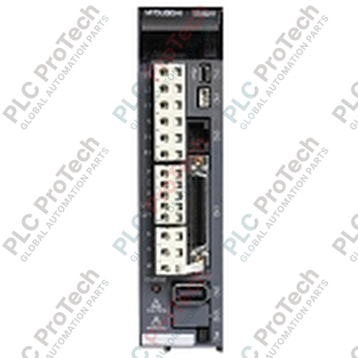
Connections and Interfaces
| Terminal / Connector |
Functional Assignment |
| L1, L2, L3 |
Main circuit power supply input (3-phase AC) |
| L11, L21 |
Control circuit power supply input (single-phase AC) |
| U, V, W |
Servo motor power output connection |
| P, C, D |
External regenerative brake resistor interface terminals |
| CN1 |
I/O signal connector (analog commands, control signals, pulse input) |
| CN2 |
Encoder feedback communication port |
| CN3 |
PC setup software (MR Configurator) serial communication port |
Empirical Engineering Insights
Alternative Models & Compatibility
When upgrading legacy motion control hardware to newer architectures, the MR-J3-500A can be replaced by the newer MELSERVO-J4 series counterpart (MR-J4-500A). However, this migration requires the use of a conversion cable adapter kit to adapt the older encoder wiring and physical mounting adapters, as the bolt holes differ. Always back up the drive parameters using MR Configurator setup software (version MRZJW3-SETUP221E or later) via the CN3 port prior to removing a faulty unit.
Application Pitfalls & Engineering Notes
At 5.0 kW, the thermal dissipation inside electrical cabinets is substantial. Ensure a minimum clearance of 40 mm above and below the amplifier for airflow. In high-cycle deceleration profiles, the built-in regenerative resistor may saturate, triggering the AL.30 (Regenerative Error) fault. Under these circumstances, you must disconnect the built-in resistor bar between the P and D terminals, and mount an external high-capacity regenerative brake resistor option (such as the MR-RB5E) across the P and C terminals.
Commissioning & Wiring Tips
For absolute positioning configurations, an external battery (MR-J3BAT) must be connected to the dedicated slot on the front of the unit to retain the encoder's multi-turn data during power-off states. Additionally, wire the control circuit power supply (L11/L21) upstream of the main power contactor. This ensures that even when the main three-phase power (L1/L2/L3) is tripped during an E-stop condition, the drive maintains absolute encoder communications and displays active error diagnostics on the built-in LED display.
Installation Guidelines
CRITICAL WARNING
Before performing mounting, wiring, or manual inspection, completely de-energize the incoming three-phase supply lines. After isolating power, wait at least 15 minutes for the internal high-voltage bus capacitors to discharge. Verify that the charge LED indicator on the front panel is completely extinguished before handling any physical terminals or connections.
1
Mechanical Mounting: Securely install the unit vertically on a flat, vibration-free panel using the rear mounting screws. Ensure the cooling fan airflow is completely unobstructed.
2
Ground Connection: Establish a robust grounding network by connecting the amplifier protective earth (PE) terminal to the cabinet's main ground bar using a low-impedance copper wire.
3
Power & Control Connections: Route control circuit (L11/L21) and main circuit (L1/L2/L3) lines separately from the motor power outputs (U/V/W) to minimize electromagnetic interference (EMI). Use shielded twisted-pair cables for signal connections.
4
Parameter Configuration: Power up the control circuit first, establish serial communication via the CN3 port, and upload/verify operational parameter configurations before enabling the main power input.