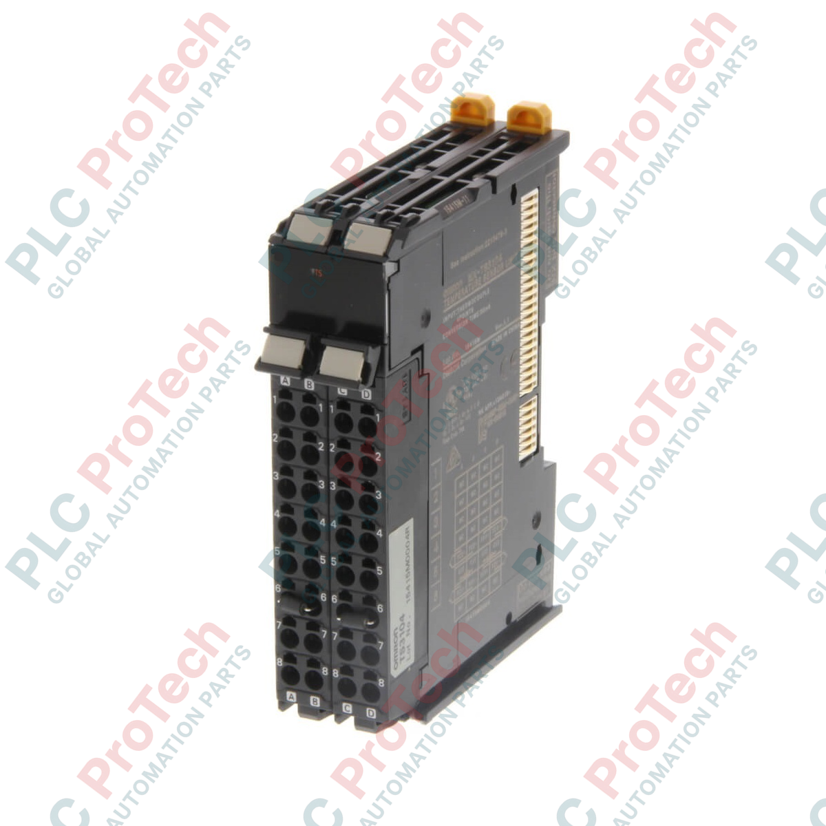
Description
Optimized for high-speed, high-density thermal monitoring, the Omron NX-TS3204 is a 4-point temperature input unit designed for direct integration within NX-series PLC backplanes and distributed I/O couplers. This unit provides dedicated interface circuitry for resistance thermometers (RTDs), allowing precise calibration and temperature feedback across demanding industrial automation systems. Featuring channel-to-channel isolation and a robust, high-resolution ADC architecture, it protects vulnerable signal loops from high common-mode voltages and electrical noise common in heavy industrial facilities.
Features
-
4 Independent Channels: Connects up to four RTD sensors to a single space-saving slice module.
-
Multi-Sensor Support: Built-in compatibility with three-wire Pt100 and Pt1000 resistance thermometers.
-
High-Speed Processing: Extremely fast input conversion time of 60 ms per unit ensures real-time thermal loop response.
-
Ultra-High Resolution: Achieves a maximum tracking resolution of 0.001 degC for critical process variables.
-
Full Electrical Isolation: Double-isolated architecture utilizing internal transformers and digital isolators between the inputs, the NX bus, and neighboring channels.
-
Toolless Termination: Features Omron push-in screwless clamping terminals for secure and vibration-resistant wiring.
Applications
- Dynamic heat-sealing control in high-speed packaging machinery.
- Multi-zone temperature tracking in plastic extrusion and molding profiles.
- Precise thermal environment monitoring in climate test chambers and cleanrooms.
- Critical pasteurization and thermal processing control in food and beverage production.
Technical Specifications Table
| Parameter |
Specification Value |
| Manufacturer |
Omron |
| Model Code |
NX-TS3204 |
| Module Type |
Temperature Input Unit (Resistance Thermometer) |
| Number of Inputs |
4 channels |
| Compatible Sensors |
Pt100 (3-wire), Pt1000 (3-wire) |
| Conversion Time |
60 ms / Unit |
| Measurement Resolution |
0.001 degC max. |
| Input Detection Current |
Approx. 0.25 mA |
| Conductor Resistance Effect |
0.06 degC/Ohm max. (Maximum allowable resistance: 20 Ohm) |
| I/O Refreshing Method |
Free-Run refreshing |
| Isolation Method |
Transformer (Power), Digital Isolator (Signal) between inputs and NX bus, plus channel-to-channel |
| Dielectric Strength |
510 VAC for 1 minute between isolated circuits (leakage current 5 mA max) |
| NX Unit Power Consumption |
1.45 W max. (CPU/CCU link); 1.05 W max. (Communications Coupler) |
| Physical Dimensions |
24 mm (W) x 100 mm (H) x 71 mm (D) |
| Weight |
0.13 kg (Net) |
Empirical Engineering Insights
Alternative Models & Compatibility
The NX-TS3204 slice integrates into both local Sysmac NX1P2 / NX102 controller structures and remote I/O nodes via EtherCAT (NX-ECC) or EtherNet/IP (NX-EIC) couplers. Unlike 2-point temperature units (such as the NX-TS2204), this 4-point design utilizes high-density 16-point push-in connectors in double rows, allowing tight DIN-rail spacing but requiring carefully planned routing for the incoming sensor cables.
Application Pitfalls & Engineering Notes
To maintain the native high accuracy of 0.001 degC, engineers must avoid asymmetric wiring resistances. While 3-wire RTDs compensate for equal line resistance, mismatched conductor resistances between the A and B/B' legs directly generate measurement offsets. Keep individual lead-wire resistances strictly below 20 Ohms, and route the signal lines away from large variable frequency drives (VFDs) and high-current motor control circuits to prevent EMI-induced drift.
Commissioning & Wiring Tips
This module relies on a warm-up period of 30 minutes before system calibration routines are initiated. When connecting solid wires or stranded wires with ferrules, simply push the wire directly into the terminal without opening the clamp with a tool. When commissioning through Sysmac Studio, ensure the input filter parameters and the target sensor type (Pt100 or Pt1000) are explicitly defined in the Unit Operation Settings, as mismatched configurations will generate erratic temperature values or fault indicators.
Installation Guidelines
CRITICAL WARNING: Completely de-energize the entire control panel, including the NX-series CPU and auxiliary external power sources, before mounting, removing, or wiring the module. Working on live systems may destroy internal sensitive digital isolators or trigger unexpected controller system errors.
1
Align the NX-TS3204 unit slide-guides with the adjacent module or bus coupler on the 35mm DIN rail.
2
Firmly slide the module until the integrated locking mechanism engages with the DIN rail with an audible click.
3
Strip the temperature sensor cables to 8-10 mm or crimp them with suitable ferrules, then insert them directly into the front-facing screwless terminal block.
4
Double-check that the field shield ground is properly clamped to the functional ground strip below the DIN rail line.