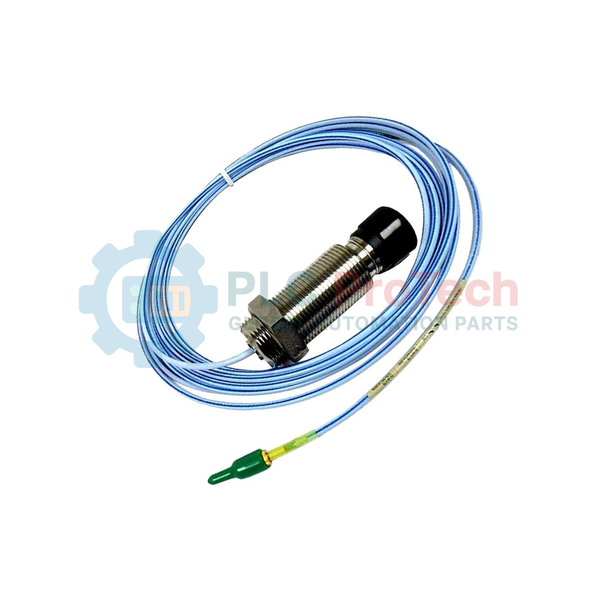
Description
Designed specifically for demanding turbomachinery displacement and vibration measurements, the Bently Nevada 330851-04-000-026-10-01-CN is a high-accuracy proximity probe within the premium 3300 XL 25 mm Proximity Transducer System. This sensor provides extended linear range capabilities, making it ideal for tracking large shaft movement and differential expansion in industrial steam turbines, gas turbines, and large-scale centrifugal compressors. The mechanical design features a smooth 1.06-inch diameter side-exit case configuration to facilitate low-clearance radial mounting while preventing cable bend stress inside tight enclosures. Constructed with a highly durable Polyetheretherketone (PEEK) probe tip and an AISI 304 stainless steel housing, the probe maintains structural and electrical integrity under severe thermal and chemical exposure.
Features
-
Smooth Case Side-Exit Design: Provides clean cable routing perpendicular to the probe axis, ideal for tight structural mounting configurations where axial clearance is limited.
-
Premium Tip Materials: Polyetheretherketone (PEEK) probe tip offers superior resistance to chemical attack, moisture absorption, and thermal degradation.
-
Triaxial FluidLoc Cable: Features a 75 ohm triaxial cable insulated with perfluoroalkoxyethylene (PFA) to prevent process fluids or lubricants from leaking through the internal cable core.
-
Stainless Steel Armor Protection: Flexible AISI 302 stainless steel armor with an additional PFA outer jacket prevents mechanical wear, abrasion, and oil ingress.
-
Extended Operating Range: Operates continuously in extreme environments ranging from -35 degC to +200 degC (-31 degF to +392 degF).
Applications
- Differential expansion and thermal growth measurements in utility steam turbines.
- Radial vibration and shaft position monitoring in large-bore gas turbines.
- Thrust position tracking inside high-speed compressor housings.
- Industrial machinery protection systems requiring compliance with API 670 standards.
Ordering Information
| Option Code |
Parameter Category |
Selected Configuration |
| 04 |
Probe Case Type |
Smooth 1.06 in diameter - Side Exit |
| 000 |
Unthreaded Length |
0 mm |
| 026 |
Overall Case Length |
26 mm |
| 10 |
Total Length |
1.0 meter (3.3 feet) |
| 01 |
Armor Option |
With SST Armor |
| CN |
Agency Approval |
Country Specific (China Approvals) |
Technical Specifications
| Manufacturer |
Bently Nevada (Baker Hughes) |
| Model Number |
330851-04-000-026-10-01-CN |
| Series |
3300 XL 25 mm |
| Probe Diameter |
25 mm (nominal) |
| Probe Tip Material |
Polyetheretherketone (PEEK) |
| Probe Case Material |
AISI 304 Stainless Steel (SST) |
| Cable Specification |
75 ohm triaxial, PFA insulated FluidLoc cable |
| Armor Material |
Flexible AISI 302 SST with protective PFA outer jacket |
| Operating Temperature |
-35 degC to +200 degC (-31 degF to +392 degF) |
| Net Weight |
0.230 kg (0.51 lbs) |
| Shipping Weight |
1.500 kg (3.31 lbs) |
| Country of Origin |
United States (U.S.A.) |
Empirical Engineering Insights
Alternative Models & Compatibility
The 330851-04-000-026-10-01-CN must always be paired with a compatible 3300 XL 25 mm Proximitor Sensor and a matching 3300 XL 25 mm extension cable. Mixing 25 mm probes with standard 3300 XL 8 mm or 11 mm proximitor models will result in catastrophic calibration mismatch, severe signal clipping, and erroneous vibration readings due to different RF bridge oscillation frequencies and linear scale factors.
Application Pitfalls & Engineering Notes
Because this is a smooth, unthreaded case configuration (Option 04) with a side-exit cable boot, special care must be taken when designing and mounting the external installation bracket. Ensure the clamping force is applied uniformly along the stainless steel smooth body and never over the side-exit cable strain relief or PEEK tip. Over-tightening brackets directly over the transition joint will damage internal coaxial connections, leading to high electrical noise (gap voltage spiking) or open-circuit faults.
Commissioning & Wiring Tips
Always maintain a minimum physical bend radius of 25.4 mm (1.0 inch) for the armored extension and probe cables. During commissioning, verify that the physical gap voltage (typically measured at the Proximitor terminal using a high-impedance digital multimeter) falls within the linear range region before locking down the probe clamp. Ensure the physical connections are insulated from grounded metal conduit paths to prevent ground loop noise from corrupting the dynamic 200 mV/mil vibration signal.
Installation Guidelines
CRITICAL FIELD WARNING
Isolate, lock out, and tag out all host equipment machinery before installation. Ensure the mounting brackets and the machine casing have returned to safe ambient temperatures and atmospheric pressures before inserting the probe assembly. Failure to isolate process pressure and machinery dynamics may result in physical injury, fluid escaping, or catastrophic sensor damage.
1
Inspect the smooth 1.06-inch diameter probe case and clean any industrial debris or shipping oil from the mounting bracket cylinder. Ensure no burrs exist inside the clamp bore.
2
Slide the probe smoothly into the mounting clamp mechanism. Ensure the side-exit cable routing path is free of sharp metallic edges and does not pinch the armored cable.
3
Connect the probe to the extension cable. Ensure the miniature coaxial connectors are dry, clean, and fully finger-tightened before applying the protective self-fluxing silicone tape or terminal connector boot.
4
Perform standard calibration gap verification by adjusting the mechanical depth until the system's DC voltage output matches the specified installation center point (refer to your specific system design documentation). Hand-tighten the mounting bracket clamp to the OEM-specified torque.