Description
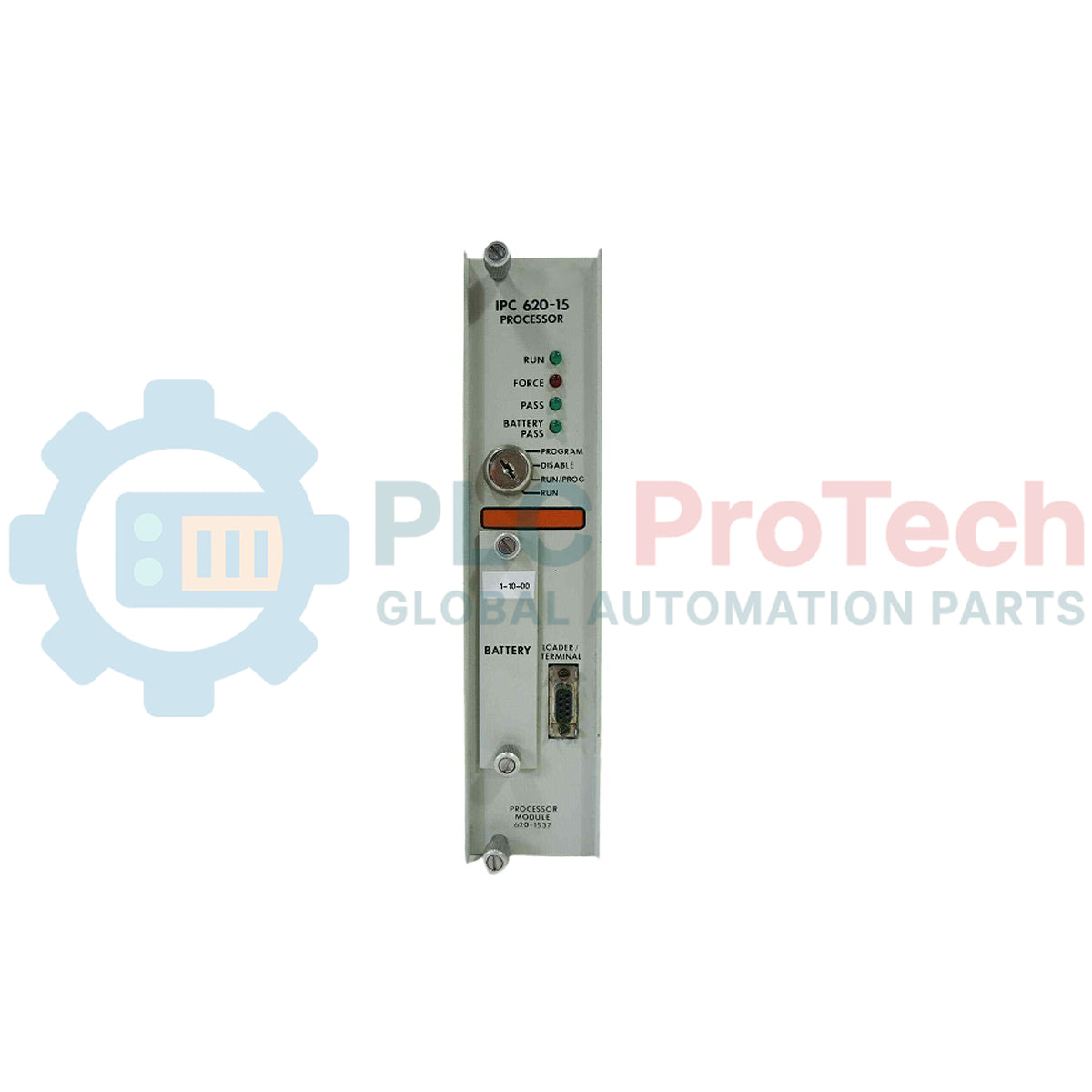
Executing core control programs and managing localized I/O configurations, the Honeywell 620-1537 serves as the primary processing engine for the legacy IPC 620 programmable logic controller assembly. Designed to operate within demanding manufacturing and processing environments, this module coordinates high-speed logic solving, backplane data communication, and configuration sequencing across standard rack systems. The legacy processor design provides long-term operational reliability for industrial facilities seeking to maintain existing control architectures without requiring complete system redesigns.
Features
- Dedicated logic processing designed specifically for the Honeywell IPC 620 backplane architecture.
- Integrated front-panel diagnostic indicators for direct monitoring of system status, processing faults, and run modes.
- Chassis-mounted design allowing secure installation into dedicated controller slots of the main system rack.
- Passive cooling structural design to maximize lifespan inside enclosed industrial control panels.
Applications
- Legacy process control loops in petrochemical and chemical refining installations.
- Assembly line automation and discrete manufacturing utilizing Honeywell IPC platform setups.
- Water treatment facilities, material handling systems, and power utility sub-station monitoring.
Technical Specifications
| Parameter |
Specification |
| Manufacturer |
Honeywell |
| Model Number |
620-1537 |
| Series |
IPC 620 |
| Module Type |
Processor Module |
| Net Weight |
1.8 kg |
| Shipping Weight (Calculated) |
3.0 kg |
| Mounting Configuration |
Dedicated Slot inside IPC 620 Chassis Rack |
Empirical Engineering Insights
Alternative Models & Compatibility
The 620-1537 processor operates specifically within legacy IPC 620 system racks. When upgrading or replacing older revisions of the Honeywell processor series, verify that your rack’s current backplane and power supply units match the electrical specifications of this module. Firmware revision compatibility must be checked against your offline programming software to ensure full recovery of the operational configuration.
Application Pitfalls & Engineering Notes
Because this is a volatile-memory dependent processor, any system battery depletion while the power is completely shut down will result in loss of volatile memory configurations. Always check status registers and replace system batteries periodically under energized conditions, or verify that an active EEPROM memory module is securely inserted to safeguard critical logic parameters.
Commissioning & Wiring Tips
Ensure the chassis ground is securely bonded before inserting the processor module. Discharging static electricity and handling the card by its polymer faceplate or plastic module edges prevents electrostatic damage to critical logic chips on the side of the circuit card.
Installation Guidelines
CRITICAL WARNING: De-energize all incoming power supplies to the IPC 620 rack system prior to physical installation or removal of the processor. Installing or pulling the module while the chassis backplane is energized can lead to irreparable electronic damage, backplane failure, or diagnostic bus faults.
1
Disconnect power from the IPC 620 rack assembly and verify that the system is fully de-energized.
2
Align the 620-1537 module card edge into the designated guide rails of the processor slot in the chassis rack.
3
Slide the module backward until the rear interface connector seats firmly with the system backplane connectors.
4
Tighten all front-panel retention screws to lock the card against environmental vibration displacement, then restore system power.