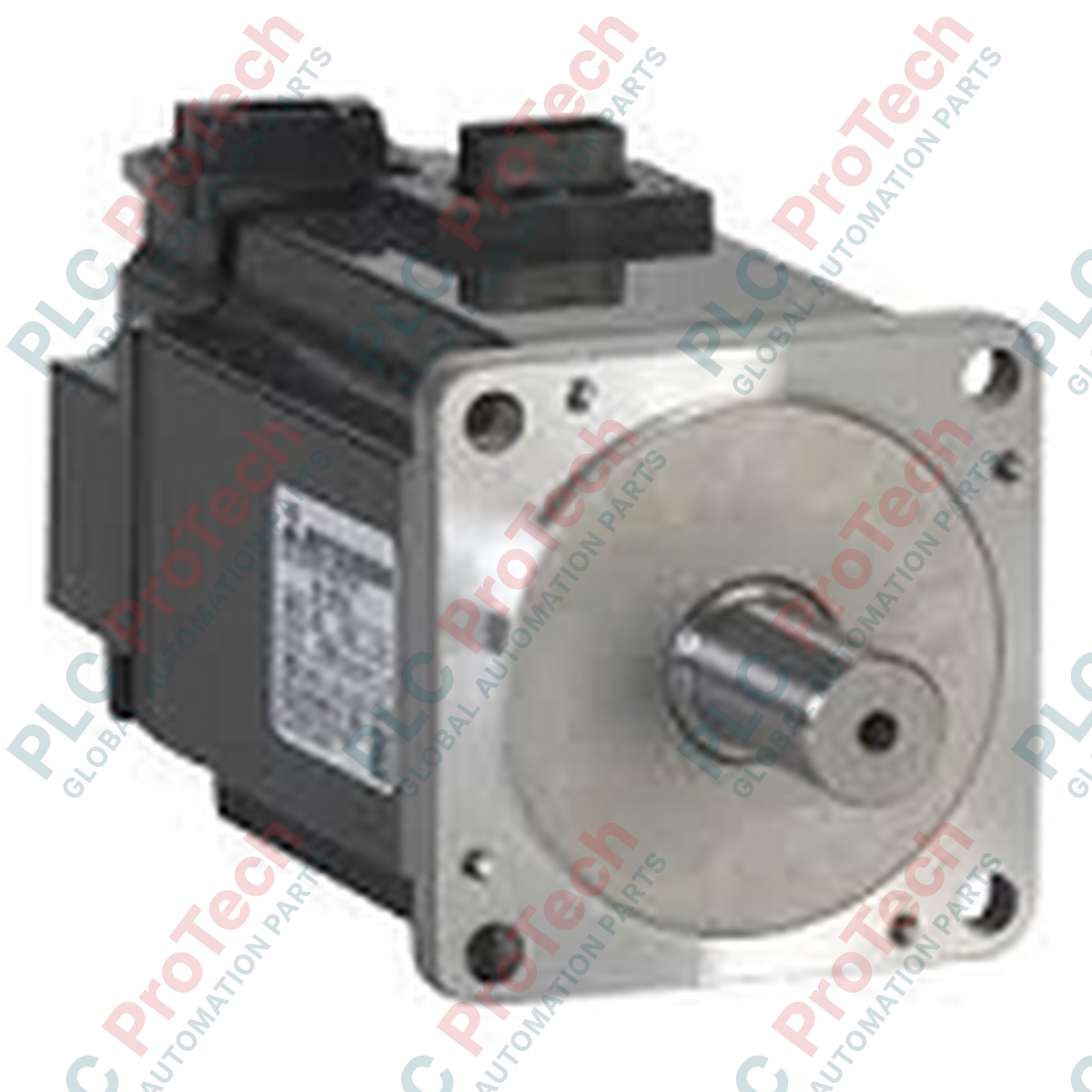
Description
Designed to execute precise velocity and torque profiles within heavy industrial environments, the Mitsubishi Electric HF-SP702 delivers dependable mechanical power when integrated into automated drive systems. This medium-inertia AC servo motor is engineered specifically to match the electrical characteristics of the MELSERVO J3 amplifier platform, ensuring rapid response times and minimal settling deviation during high-duty cycling operations.
Features
- Medium rotor inertia configuration optimized for stable load matching in applications with fluctuating mechanical loads.
- High-resolution absolute/incremental encoder integration to enable ultra-precise closed-loop positioning feedback.
- Robust IP67 protective sealing (excluding the shaft-through portion) to withstand harsh oil, dust, and moisture environments.
- Standard heavy-duty MS circular connectors for secure power and encoder wiring terminations.
Applications
- Multi-axis CNC machining centers and automated metal forming machinery.
- High-speed industrial material handling and gantry system positioning.
- Heavy-duty packaging and bottling machinery requiring precise speed control.
- Automotive welding and assembly line positioning axes.
Technical Specifications
| Parameter |
Specification |
| Manufacturer |
Mitsubishi Electric |
| Model Number |
HF-SP702 |
| Product Series |
MELSERVO J3 Series |
| Compatible Servo Amplifier |
MR-J3-700A / MR-J3-700B / MR-J3-700T |
| Rated Output Capacity |
7.0 kW |
| Rated Speed |
2000 r/min |
| Maximum Rotation Speed |
3000 r/min |
| Rated Torque |
33.4 N-m |
| Power Facility Capacity |
10 kVA |
| Supply Voltage Class |
200 VAC |
| Enclosure Protection Rating |
IP67 (excludes shaft-through portion) |
| Shipping Weight (Calculated) |
33 kg (72.7 lbs) |
| Package Dimensions (Calculated) |
450 mm x 300 mm x 280 mm |
Empirical Engineering Insights
Alternative Models & Compatibility
While native to the MR-J3 amplifier series, the HF-SP702 can be migrated to the newer MR-J4 series (e.g., MR-J4-700A) by configuring the drive for J3 compatibility mode. This migration requires designated conversion cables for both the high-resolution encoder line and the main power connector due to differences in physical terminal sizing and pinouts.
Application Pitfalls & Engineering Notes
Operating this motor at continuous high duty cycles requires adequate heat dissipation. Ensure it is bolted to a steel or aluminum mounting flange of at least 400 mm x 400 mm x 20 mm to prevent thermal alarms on the drive. For vertical applications, avoid using this standard model; instead, deploy the brake-equipped variant (HF-SP702B) to prevent load drop during emergency stops or power failures.
Commissioning & Wiring Tips
To eliminate electromagnetic interference (EMI) issues with high-resolution feedback signals, ensure the encoder cable shield is grounded directly to the amplifier cabinet's main backplate. Power cables carrying the high-frequency PWM drive outputs must be routed separately from sensor and control lines, maintaining a minimum physical clearance of 30 cm.
Installation Guidelines
CRITICAL WARNING: Verify that all incoming three-phase AC power sources are completely locked out and tagged out before beginning the installation process. Wait a minimum of 20 minutes after de-energizing to allow the internal bus capacitors of the MR-J3 amplifier to fully discharge (verify zero voltage across the L+ and L- terminals with a calibrated multimeter).
1
Mechanical Coupling: Align the motor shaft carefully with the load input. Use high-quality flexible couplings to prevent radial or axial force overloads on the motor bearings during operation.
2
Cable Connection: Securely thread the MS circular connectors for both power and encoder cables. Ensure the rubber O-rings are fully seated within the connector threads to maintain the integrity of the IP67 moisture seal.
3
Grounding Setup: Terminate the motor ground wire to the designated grounding point on the amplifier base, securing it tightly to prevent high-frequency noise leakage.