Description
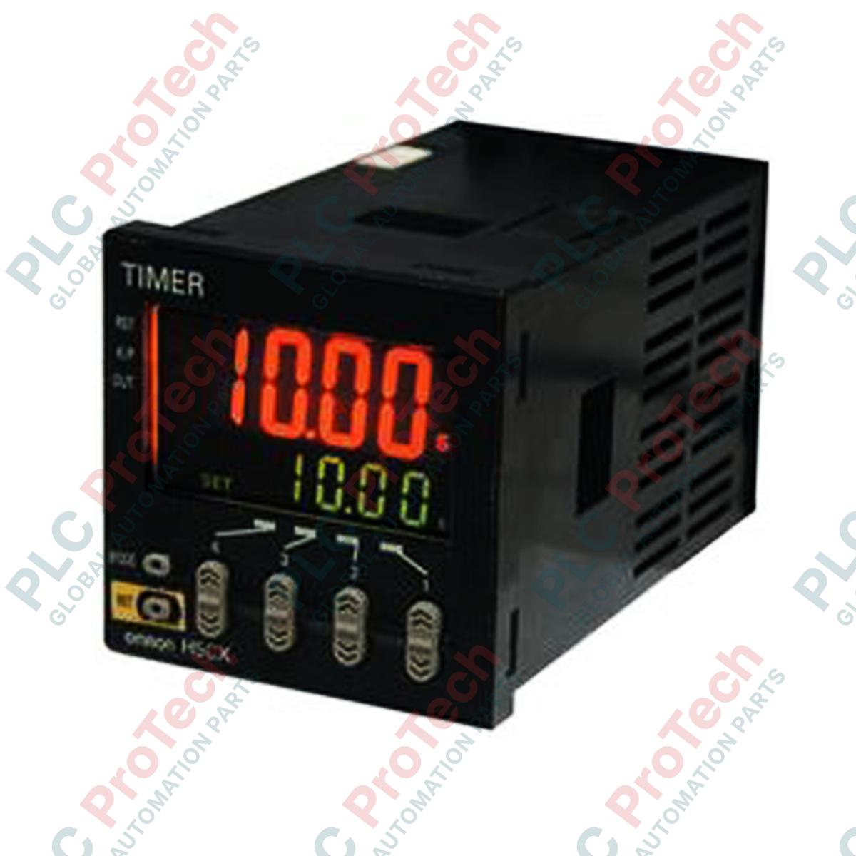
Designed for precise temporal control in complex industrial automation architectures, the Omron H5CX-A11-N is an ultra-compact, 11-pin socket-mount digital multifunction timer operating on a wide 100 to 240 VAC supply voltage. This highly reliable control component integrates advanced digital timing functions with a clear, dual-color display interface, enabling seamless setup and immediate operational feedback directly on the plant floor. Engineered for longevity and performance, the H5CX-A11-N supports multiple timing modes and input configurations to easily adapt to standard electrical panels and machinery control circuits.
Key Features
-
Dual-Color Display: Highly legible PV (Present Value) display in 12 mm red characters, complemented by a 6 mm green SV (Set Value) display for instantaneous status verification.
-
Versatile Operation Modes: Supports key timing configurations including ON-delay, OFF-delay, Repeat Cycle, and Signal ON/OFF-delay to match complex automation logic.
-
Flexible Mounting: Equipped with an 11-pin round socket connector, facilitating rapid DIN-rail chassis mounting or flush panel integration.
-
Input Compatibility: Accepts both NPN (no-voltage) and PNP (voltage) external inputs for flexible sensor and controller integration.
-
Robust Memory Protection: Internal EEPROM backup retains vital user configurations and program parameters during unexpected power losses.
Applications
-
Packaging Equipment: Managing seal jaw timing, bag sealing cycles, and sorting conveyor intervals.
-
Thermal Process Units: Regulating precise heating, curing, and dwell times in industrial ovens and dryers.
-
Fluid & Pump Management: Managing alternate-pump cycling and automated backwash flush intervals in water systems.
-
Machine Tool Lubrication: Driving cyclic lubrication solenoids to protect high-speed bearing housings.
Technical Specifications
| Parameter |
Value / Specification |
| Manufacturer |
Omron Industrial Automation |
| Model Code |
H5CX-A11-N |
| Operating Voltage |
100 to 240 VAC, 50/60 Hz |
| Allowable Voltage Range |
85% to 110% of rated supply voltage |
| Power Consumption |
Approx. 9.4 VA (at 240 VAC) |
| Control Output |
SPDT Contact Output: 5 A at 250 VAC / 30 VDC (resistive load) |
| External Input Types |
Signal, Reset, and Gate Inputs |
| Input Logic Options |
No-voltage input (NPN contact/transistor) / Voltage input (PNP) |
| Character Height |
Present Value (PV): 12 mm (Red); Set Value (SV): 6 mm (Green) |
| Case Dimensions |
48 x 48 x 84.1 mm (1/16 DIN) |
| Ambient Operating Temp |
-10 to 55 degC (with no icing or condensation) |
| Storage Temperature |
-25 to 65 degC (with no icing or condensation) |
| Shipping Weight (Calculated) |
0.30 kg |
| Package Dimensions (Calculated) |
110 x 60 x 60 mm |
Connections and Interfaces
The device utilizes a standard 11-pin round socket configuration for all electrical interfacing. Secure proper matching connections using the pinout matrix below:
| Terminal Pin No. |
Function Assignment |
| Pin 1 |
External Input Common (0 V reference) |
| Pin 2 |
Power Supply Terminal (Neutral / L2) |
| Pin 3 |
Signal Input (Timer Start) |
| Pin 4 |
Reset Input |
| Pin 5 |
Gate Input (Timer Pause) |
| Pin 8 |
Control Output - NC (Normally Closed Contact) |
| Pin 9 |
Control Output - NO (Normally Open Contact) |
| Pin 10 |
Power Supply Terminal (Line / L1) |
| Pin 11 |
Control Output - COM (Common Contact) |
| Pins 6, 7 |
No Internal Connection (Do not wire) |
Alternative Models & Compatibility
The modern H5CX-A11-N directly succeeds older non-N legacy models (e.g., H5CX-A11). This updated model features enhanced display brightness and updated firmware parameter structures. When migrating to the "N" designated unit, verify parameter configurations through the front-key system as factory default settings may vary slightly from obsolete revisions. Physical form-factor, 11-pin terminal block mapping, and mounting footprints remain strictly backward-compatible.
Application Pitfalls & Engineering Notes
Avoid routing signal inputs (Pins 1, 3, 4, 5) inside the same conduit run as heavy power lines or AC motor leads to prevent electromagnetic interference. Standard high-frequency spikes can bypass the input filter and trigger ghost starts or unexpected resets. If mounting in unventilated electrical panels alongside high-current components (like motor drives or solid-state relays), ensure local ambient temperatures do not continuously exceed the 55 degC operational threshold.
Commissioning & Wiring Tips
Before powering up the system, determine if the external control device operates on open-collector NPN or source PNP logic. The internal input selector must be correctly set via the operational keys to align with this logic. Misaligned configuration may prevent the timer from recognizing signal input pulses. When utilizing the Reset function, ensure a minimum contact pulse width of 1 ms or 20 ms is selected based on key-bounce filtration requirements in the internal parameter menu.
Installation Guidelines
CRITICAL WARNING: Verify that all AC power feeds to the panel are physically isolated, locked out, and tagged out prior to making or modifying socket wiring. Failure to do so can result in fatal electrical shock, terminal short circuits, and destruction of internal logic boards.
1
Install the compatible 11-pin socket (e.g., Omron PF113A-E) onto standard 35 mm DIN rail or panel surface cutout using verified mounting accessories.
2
Terminate power conductors (100 to 240 VAC) securely to Pin 2 and Pin 10 of the base socket, matching proper line/neutral polarization.
3
Wire sensor, reset, or logic contact inputs to Pins 1, 3, 4, and 5 using high-quality shielded signal cable with clean cable termination sleeves.
4
Insert the physical digital timer housing firmly into the socket, ensuring the alignment key in the center of the pin group seats fully without bending the connection contacts. Engage any securing clips if operating in high-vibration applications.