BECKHOFF

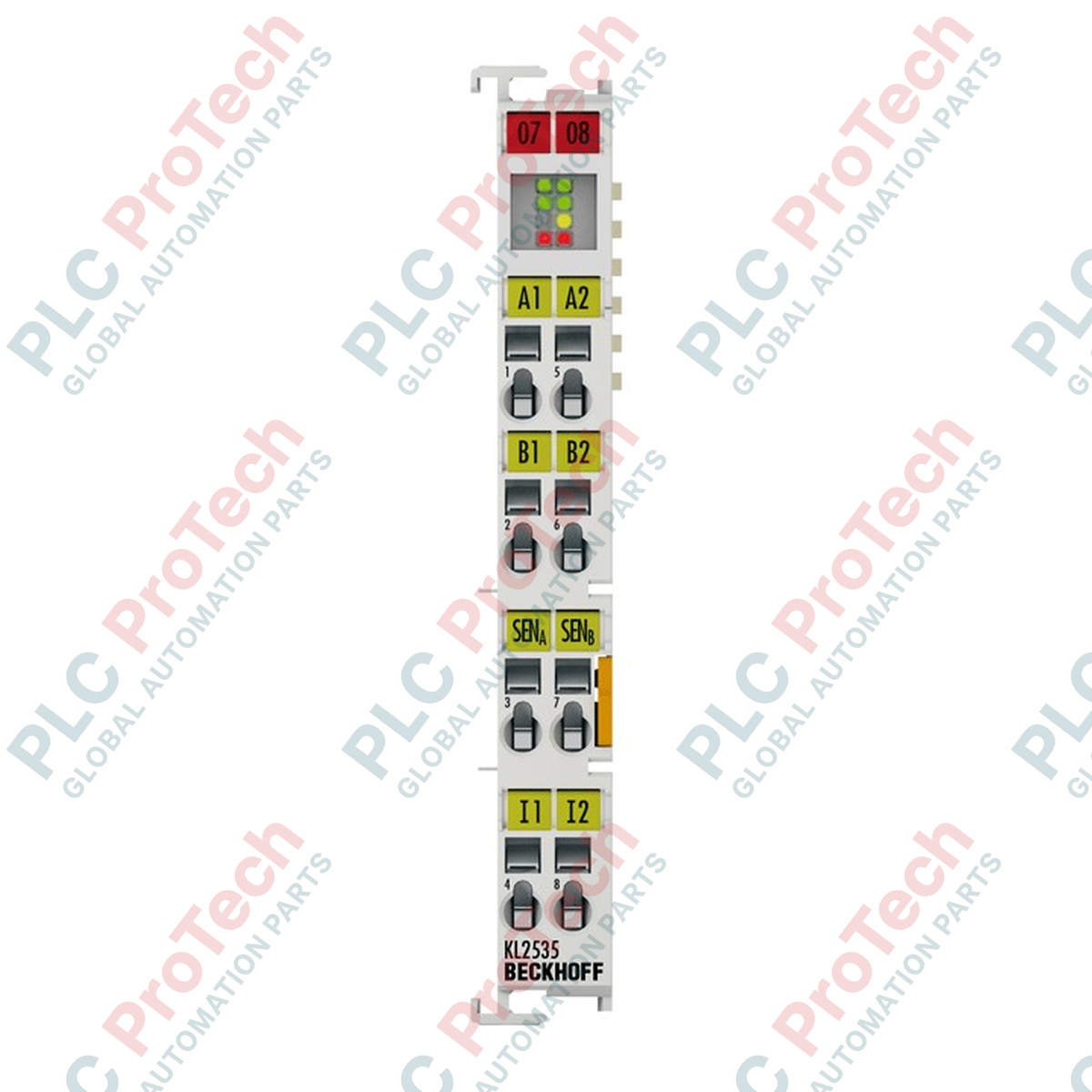
Beckhoff KL2535 Bus Terminal 2-Channel PWM Output Module

SKU KL2535

Disponibile
  • 12-month warranty
  • Free returns within 30 days
  • Manufacturer: BECKHOFF
  • Product No.: KL2535
  • Origin Germany
  • Product Type: Bus Terminals
  • Payment: T/T, Western Union
  • Weight: 0.5 kg
  • Dimensions: 12.5 cm x 8.0 cm x 2.4 cm
  • Shipping port: Xiamen
  • Warranty: 12 months

Tags

Quantità

Product Description

Description

Directing the precise power distribution to inductive loads, the Beckhoff KL2535 represents a high-efficiency 2-channel pulse-width modulation (PWM) output terminal integrated into the robust K-bus architecture. This industrial-grade output terminal is engineered specifically for control applications requiring current-regulated output power, such as proportional valves, solenoids, and magnetic coils. Utilizing high-frequency switching technology, it permits seamless duty-cycle adjustments from 0% to 100% with short-circuit and thermal-overload protection standard across both channels. Designed for DIN-rail deployment, the module maintains a compact form factor while providing galvanically isolated, high-resolution control signals directly from the standard PLC process image.

Key Features

  • Dual PWM Outputs: Controls two independent channels rated at 24 V DC with an output current capacity up to 1 A per channel.
  • High-Frequency Modulated Control: Operates at a default PWM clock frequency of 36 kHz, ensuring ripple-reduced current stability in inductive loads.
  • Comprehensive Self-Protection: Integrated short-circuit protection and cooperative thermal overload shutdown preserve system longevity.
  • Robust Galvanic Isolation: Provides up to 500 V electrical isolation between the internal K-bus and the field potential.
  • Compact Form Factor: Standard 12 mm bus terminal width optimizes control cabinet real estate.

Applications

  • Proportional Valve Control: Modulates pilot valves, hydraulic directional valves, and pneumatic control assemblies.
  • Electromagnetic Solenoids: Manages current limits and holding states for heavy-duty industrial relays and linear actuators.
  • Thermal Loop Elements: Drives resistive heating elements and cooling fans using high-frequency duty cycles.

Technical Specifications

Parameter Specification Value
Manufacturer Beckhoff Automation
Model / Article Number KL2535
Number of Outputs 2
Nominal Voltage 24 V DC (-15% / +20%)
Load Compatibility Inductive (> 1 mH), solenoid valves, coils
Max. Output Current 2 x 1 A (short-circuit and thermal-overload proof)
PWM Frequency 36 kHz
Duty Factor 0% to 100% (current-controlled)
Resolution Max. 12-bit
Electrical Isolation 500 V (K-bus / field potential)
Current Consumption (K-bus) Typically 60 mA
Current Consumption (Power Contacts) Load current only
Process Image Width 48 inputs/outputs (2 x 16-bit data, 2 x 8-bit control/status)
Configuration Address-free; configures via Bus Coupler or controller
Operating Temperature Range 0 to +55 degC
Storage Temperature Range -25 to +85 degC
Relative Humidity Limit 95%, non-condensing
Protection Rating IP20
Net Weight 55 g
Shipping Weight (Calculated) 0.25 kg
Package Dimensions (Calculated) 12.5 cm x 8.0 cm x 2.4 cm

Connections and Interfaces

Terminal Connection Point Circuit Allocation / Function
Point 1 Output 1+ (PWM Current Output 1)
Point 5 Output 1- (PWM Current Return 1)
Point 2 Output 2+ (PWM Current Output 2)
Point 6 Output 2- (PWM Current Return 2)
Point 3 +24 V DC Field Power Supply Contact
Point 7 0 V DC Field Power Supply Contact
Point 4 & 8 Shield / Protective Earth (PE) Connection

Empirical Engineering Insights

Alternative Models & Compatibility

The KL2535 operates within standard Beckhoff K-bus systems. For architectures utilizing EtherCAT protocols, the EL2535 EtherCAT Terminal serves as the natural functional migration path, matching form factors and general electrical outputs but adapting to the EtherCAT E-bus interface. If upgrading older standard terminals, verify that your active Bus Coupler (such as the BK3120, BK9000, or BC9000) is running compatible firmware to parse the 48-bit control and status registers allocated by the KL2535.

Application Pitfalls & Engineering Notes

Thermal integration is a critical factor when driving both channels at their maximum 1 A current limits continuously. Under high ambient temperatures close to the 55 degC limit, proper vertical mounting and standard 10 mm lateral spacing from high-heat components are highly recommended. Note that because the PWM clock operates at 36 kHz, high-frequency current ripples can induce minor inductive heating inside solenoids if the load inductance is lower than 1 mH; verify load parameters prior to continuous cycling.

Commissioning & Wiring Tips

To minimize high-frequency electromagnetic emissions generated by the 36 kHz carrier signal, always utilize twisted-pair, shielded cabling for all load connections. Connect the cable shield directly to the designated PE terminal points (4 and 8) on the KL2535 housing or the system grounding rail. Avoid running output wires parallel to analog sensor cables to prevent crosstalk noise.

Installation Guidelines

CRITICAL SAFETY WARNING:

Isolate and lock out all electrical control and field power systems before installing, removing, or wiring the module. Handling terminals with active field potential can lead to controller-bus degradation, damage to output channels, or unexpected, hazardous actuation of connected mechanical actuators.

1
Align the KL2535 guide slots with the adjacent Bus Terminal and slide onto the standard DIN rail (EN 60715) until the metallic latch clicks securely.
2
Apply firm lateral pressure to ensure the integrated gold-plated tongue-and-groove K-bus contacts seat tightly with adjacent units.
3
Terminate field wiring by pressing the terminal clamp tool into the actuation slot and inserting stripped wire conductors (up to 2.5 mm squared) into the connection point.
4
Ensure the power contacts are connected to an isolated external 24 V DC power source to energize the output driver circuitry.
Shipping & Returns

Global Express Shipping

  • Standard Delivery: 4–6 business days via DHL, FedEx, and UPS.
  • Express Dispatch: Same-day dispatch for in-stock orders placed before 2:00 PM (GMT+8).
  • Worldwide Coverage: Serving over 150 countries.

Returns & Warranty

  • 30-Day Guarantee: Returns accepted for in-stock products in original, factory-sealed packaging.
  • 12-Month Warranty: Every industrial component is backed by our technical warranty.
FAQ
What is the primary function of the KL2535 Bus Terminal?
It is a 2-channel pulse-width modulation (PWM) output terminal designed to control inductive loads like solenoid valves and coils using 24V DC current-controlled signals.
What protection features are built into this module?
The module contains built-in short-circuit protection and thermal-overload protection that shields both output channels from damage under heavy fault conditions.
Does this terminal require a separate power supply for the field outputs?
Yes, while K-bus logic is powered internally by the Bus Coupler, the output current and inductive loads must be powered by feeding 24V DC to the terminal's power contacts.
Can I use the KL2535 in an EtherCAT control network?
Yes, but you must plug it into an EtherCAT-compatible K-bus coupler, such as the BK1120 or BK1250, or use the direct EtherCAT equivalent EL2535 terminal.
Reviews

KL2535

Stock & lead time on request

Call
1 su 1

Beckhoff KL2535 Bus Terminal 2-Channel PWM Output Module

Only 10 item(s) left in stock
  • Manufacturer: BECKHOFF

  • Product No.: KL2535

  • Country of origin:Germany

  • Product Type: Bus Terminals

  • Payment: T/T, Western Union

  • Weight: 500g

  • Dimensions: 12.5 cm x 8.0 cm x 2.4 cm

  • Shipping port: Xiamen

  • Warranty: 12 months

Quantità
Visualizza dettagli completi

Product Description

Description

Directing the precise power distribution to inductive loads, the Beckhoff KL2535 represents a high-efficiency 2-channel pulse-width modulation (PWM) output terminal integrated into the robust K-bus architecture. This industrial-grade output terminal is engineered specifically for control applications requiring current-regulated output power, such as proportional valves, solenoids, and magnetic coils. Utilizing high-frequency switching technology, it permits seamless duty-cycle adjustments from 0% to 100% with short-circuit and thermal-overload protection standard across both channels. Designed for DIN-rail deployment, the module maintains a compact form factor while providing galvanically isolated, high-resolution control signals directly from the standard PLC process image.

Key Features

  • Dual PWM Outputs: Controls two independent channels rated at 24 V DC with an output current capacity up to 1 A per channel.
  • High-Frequency Modulated Control: Operates at a default PWM clock frequency of 36 kHz, ensuring ripple-reduced current stability in inductive loads.
  • Comprehensive Self-Protection: Integrated short-circuit protection and cooperative thermal overload shutdown preserve system longevity.
  • Robust Galvanic Isolation: Provides up to 500 V electrical isolation between the internal K-bus and the field potential.
  • Compact Form Factor: Standard 12 mm bus terminal width optimizes control cabinet real estate.

Applications

  • Proportional Valve Control: Modulates pilot valves, hydraulic directional valves, and pneumatic control assemblies.
  • Electromagnetic Solenoids: Manages current limits and holding states for heavy-duty industrial relays and linear actuators.
  • Thermal Loop Elements: Drives resistive heating elements and cooling fans using high-frequency duty cycles.

Technical Specifications

Parameter Specification Value
Manufacturer Beckhoff Automation
Model / Article Number KL2535
Number of Outputs 2
Nominal Voltage 24 V DC (-15% / +20%)
Load Compatibility Inductive (> 1 mH), solenoid valves, coils
Max. Output Current 2 x 1 A (short-circuit and thermal-overload proof)
PWM Frequency 36 kHz
Duty Factor 0% to 100% (current-controlled)
Resolution Max. 12-bit
Electrical Isolation 500 V (K-bus / field potential)
Current Consumption (K-bus) Typically 60 mA
Current Consumption (Power Contacts) Load current only
Process Image Width 48 inputs/outputs (2 x 16-bit data, 2 x 8-bit control/status)
Configuration Address-free; configures via Bus Coupler or controller
Operating Temperature Range 0 to +55 degC
Storage Temperature Range -25 to +85 degC
Relative Humidity Limit 95%, non-condensing
Protection Rating IP20
Net Weight 55 g
Shipping Weight (Calculated) 0.25 kg
Package Dimensions (Calculated) 12.5 cm x 8.0 cm x 2.4 cm

Connections and Interfaces

Terminal Connection Point Circuit Allocation / Function
Point 1 Output 1+ (PWM Current Output 1)
Point 5 Output 1- (PWM Current Return 1)
Point 2 Output 2+ (PWM Current Output 2)
Point 6 Output 2- (PWM Current Return 2)
Point 3 +24 V DC Field Power Supply Contact
Point 7 0 V DC Field Power Supply Contact
Point 4 & 8 Shield / Protective Earth (PE) Connection

Empirical Engineering Insights

Alternative Models & Compatibility

The KL2535 operates within standard Beckhoff K-bus systems. For architectures utilizing EtherCAT protocols, the EL2535 EtherCAT Terminal serves as the natural functional migration path, matching form factors and general electrical outputs but adapting to the EtherCAT E-bus interface. If upgrading older standard terminals, verify that your active Bus Coupler (such as the BK3120, BK9000, or BC9000) is running compatible firmware to parse the 48-bit control and status registers allocated by the KL2535.

Application Pitfalls & Engineering Notes

Thermal integration is a critical factor when driving both channels at their maximum 1 A current limits continuously. Under high ambient temperatures close to the 55 degC limit, proper vertical mounting and standard 10 mm lateral spacing from high-heat components are highly recommended. Note that because the PWM clock operates at 36 kHz, high-frequency current ripples can induce minor inductive heating inside solenoids if the load inductance is lower than 1 mH; verify load parameters prior to continuous cycling.

Commissioning & Wiring Tips

To minimize high-frequency electromagnetic emissions generated by the 36 kHz carrier signal, always utilize twisted-pair, shielded cabling for all load connections. Connect the cable shield directly to the designated PE terminal points (4 and 8) on the KL2535 housing or the system grounding rail. Avoid running output wires parallel to analog sensor cables to prevent crosstalk noise.

Installation Guidelines

CRITICAL SAFETY WARNING:

Isolate and lock out all electrical control and field power systems before installing, removing, or wiring the module. Handling terminals with active field potential can lead to controller-bus degradation, damage to output channels, or unexpected, hazardous actuation of connected mechanical actuators.

1
Align the KL2535 guide slots with the adjacent Bus Terminal and slide onto the standard DIN rail (EN 60715) until the metallic latch clicks securely.
2
Apply firm lateral pressure to ensure the integrated gold-plated tongue-and-groove K-bus contacts seat tightly with adjacent units.
3
Terminate field wiring by pressing the terminal clamp tool into the actuation slot and inserting stripped wire conductors (up to 2.5 mm squared) into the connection point.
4
Ensure the power contacts are connected to an isolated external 24 V DC power source to energize the output driver circuitry.

What is the primary function of the KL2535 Bus Terminal?

It is a 2-channel pulse-width modulation (PWM) output terminal designed to control inductive loads like solenoid valves and coils using 24V DC current-controlled signals.

What protection features are built into this module?

The module contains built-in short-circuit protection and thermal-overload protection that shields both output channels from damage under heavy fault conditions.

Does this terminal require a separate power supply for the field outputs?

Yes, while K-bus logic is powered internally by the Bus Coupler, the output current and inductive loads must be powered by feeding 24V DC to the terminal's power contacts.

Can I use the KL2535 in an EtherCAT control network?

Yes, but you must plug it into an EtherCAT-compatible K-bus coupler, such as the BK1120 or BK1250, or use the direct EtherCAT equivalent EL2535 terminal.

Global Express Shipping

  • Standard Delivery: 4-6 Business Days via DHL, FedEx, and UPS.
  • Express Dispatch: Same-day dispatch for in-stock orders placed before 2:00 PM (GMT+8).
  • Worldwide Coverage: Serving over 150 countries, including rapid delivery to Saudi Arabia and UAE.

Returns & Warranty

  • 30-Day Guarantee: Returns accepted for in-stock products in original, factory-sealed packaging.
  • 12-Month Warranty: Every industrial component is backed by our professional technical warranty.

Orders are processed and delivered Monday-Friday (excluding public holidays).


For full eligibility, restocking fees, and international return details, please view our official Refund & Return Policy .

TECHNICAL SPECIFICATIONS

Country of origin
Germany

Technical knowledge

1756-L73 Firmware Upgrade Guide: v19 vs v21/v31 Decision

Replacing a 1756-L73 does not automatically mean upgrading its firmware. This guide compares v19.013, v21.011 and v31.011, focusing on project compatibility, HMI communications, legacy networks and...

Implementing 3-Switch XOR Ladder Logic with Internal Bit

Implement a 3-SPST switch XOR light circuit in LogixPro or RSLogix 500 using an internal relay bit. Includes truth tables, boolean equations, and verified.

Building a Modbus RTU Network with CompactLogix and DeltaV

Integrate Allen-Bradley CompactLogix, Caterpillar ATS, and generators into DeltaV DCS over Modbus RTU. Covers ProSoft MVI69-MCM, Miille DIN266 gateways.

ONS Instruction Not Energizing OTE in Studio 5000 Ladder Logic

ONS instruction fires but the OTE coil never latches in Studio 5000 because the one-shot is only true for one scan. Use OTL/OTU or seal-in logic instead.

Kinetix 5500 EtherNet/IP Network Switch Requirements and Topology

Configure Allen-Bradley Kinetix 5500 servo drives on EtherNet/IP. Covers CIP Sync, IEEE 1588 V2 timing, Stratix selection, DLR topology, and HMI.

Moving Average Filtering in DCS and PLC Analog Control

A moving-average filter is the sliding-window smoother most instrument engineers drop into DCS and PLC analog paths. Here is how the window works, how N and sample time set lag, and when a...