BECKHOFF

BECKHOFF KS3182 Analog Input Bus Terminal

SKU KS3182

Disponibile
  • 12-month warranty
  • Free returns within 30 days
  • Manufacturer: BECKHOFF
  • Product No.: KS3182
  • Origin Germany
  • Product Type: Bus Terminals
  • Payment: T/T, Western Union
  • Weight: 0.07 kg
  • Dimensions: 12 mm x 100 mm x 68 mm
  • Shipping port: Xiamen
  • Warranty: 12 months

Tags

Quantità

Product Description

Description

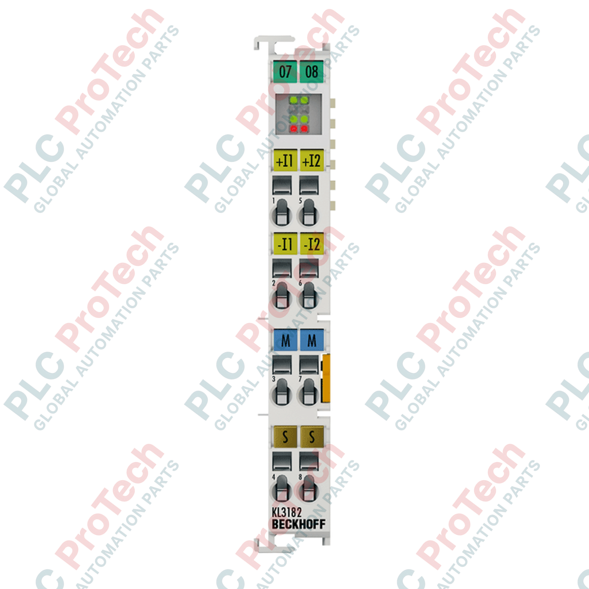
The BECKHOFF KS3182 is a high-accuracy, 2-channel analog input Bus Terminal designed for the precise measurement of differential voltage signals in the range of -2 V to +2 V. Operating within the K-bus system, this module digitizes analog process signals with a high resolution of 16 bits, ensuring reliable performance in demanding industrial measurement tasks. The terminal features a pluggable wiring design that simplifies maintenance and wiring assembly compared to standard terminal housings.

Equipped with galvanic isolation between the input channels and the K-bus, the BECKHOFF KS3182 protects sensitive control electronics from field-side voltage anomalies. Configurable parameters, such as conversion times and internal software filters, allow engineers to tailor the terminal behavior to specific system dynamics and signal conditions.

Features

  • Two differential analog input channels for high-accuracy voltage measurement.
  • 16-bit analog-to-digital resolution for precise signal processing.
  • Pluggable connection technology (KS-series terminal housing) for fast, tool-free wiring exchange.
  • Integrated galvanic isolation of 500 V between the K-bus and the input signals.
  • Configurable 50 Hz filter and adjustable conversion time of 140 ms.
  • Direct integration into the Beckhoff K-bus system with status diagnostics.

Applications

  • Precise voltage monitoring and differential signal processing in industrial automation.
  • Connection of differential output sensors within control cabinets.
  • De-centralized data acquisition systems utilizing the Beckhoff K-bus architecture.
  • General test stand configurations and process engineering environments.

Technical Specifications

Signal and I/O

Parameter Specification
Number of inputs 2 differential inputs
Signal voltage -2 to +2 V
Resolution 16 bit
Measuring error < ±0.05% (relative to full scale value)
Internal resistance > 70 kOhm
Common-mode voltage UCM Max. 10 V
Conversion time 140 ms (configurable)
Filter 50 Hz (configurable)

Electrical Data

Parameter Specification
Power supply Via the K-bus
Current consumption K-bus Typ. 85 mA
Current consumption power contacts Not used
Electrical isolation 500 V (K-bus/signal voltage)
Bit width in process image Input: 2 x 16-bit data (2 x 8-bit control/status optional)

Physical and Mechanical

Parameter Specification
Design form Terminal housing with pluggable wiring level
Wiring connection Spring actuation by screwdriver
Connection cross-section (solid) 0.08 to 1.5 mm² (AWG 28...16)
Connection cross-section (stranded) 0.08 to 1.5 mm² (AWG 28...16)
Connection cross-section (flexible) 0.14 to 1.5 mm² (AWG 26...16)
Stripping length 9 to 10 mm
Dimensions (W x H x D) 12 mm x 100 mm x 68 mm
Weight Approx. 0.07 kg (70 g)
Mounting 35 mm DIN rail conforming to EN 60715 with lock

Environmental and Certifications

Parameter Specification
Operating temperature 0 degC to +55 degC
Storage temperature -25 degC to +85 degC
Relative humidity 95%, no condensation
Vibration/shock resistance Conforms to EN 60068-2-6 / EN 60068-2-27
EMC immunity/emission Conforms to EN 61000-6-2 / EN 61000-6-4
Protection rating IP20
Approvals/markings CE, UL, ATEX
Ex marking II 3 G Ex nA IIC T4 Gc

Connections / Interfaces

Terminal Point Function
Input 1+ Positive analog input channel 1
Input 1- Negative analog input channel 1
Shield 1 Shield connection channel 1
Input 2+ Positive analog input channel 2
Input 2- Negative analog input channel 2
Shield 2 Shield connection channel 2

Installation Guidelines

  1. Ensure the system controller and all power supplies connected to the K-bus and field wiring are completely de-energized before beginning installation.
  2. Mount the Bus Terminal onto a standard 35 mm DIN rail conforming to EN 60715, ensuring the lock mechanism clicks securely.
  3. Insert field signal wires into the pluggable terminal block using a compatible screwdriver to actuate the spring-clamp contacts. Verify wire stripping lengths are between 9 and 10 mm.
  4. Connect the shield connections directly to a suitable ground potential to minimize electromagnetic interference on the analog signal inputs.
  5. Apply power to the system and verify diagnostic LED activity to ensure normal communication with the bus coupler or master controller.
Shipping &amp; Returns

Global Express Shipping

  • Standard Delivery: 4–6 business days via DHL, FedEx, and UPS.
  • Express Dispatch: Same-day dispatch for in-stock orders placed before 2:00 PM (GMT+8).
  • Worldwide Coverage: Serving over 150 countries.

Returns & Warranty

  • 30-Day Guarantee: Returns accepted for in-stock products in original, factory-sealed packaging.
  • 12-Month Warranty: Every industrial component is backed by our technical warranty.
FAQ
What is the primary difference between the Beckhoff KS3182 and KL3182 Bus Terminals?
The BECKHOFF KS3182 features a pluggable wiring level that allows the entire wiring block to be disconnected from the main housing, whereas the KL3182 uses standard non-pluggable terminals, simplifying unit replacement and installation in high-uptime systems.
What signal type and voltage range does the BECKHOFF KS3182 support?
The BECKHOFF KS3182 is designed to measure differential analog voltage signals in a range from -2 V to +2 V with an outstanding measuring error of less than ±0.05% relative to the full scale value.
Does the BECKHOFF KS3182 require an external 24 V feed for its internal electronics?
No, the BECKHOFF KS3182 draws all required operating power directly from the internal K-bus (typically 85 mA), meaning it does not consume current from the power contacts of adjacent terminals.
What is the default conversion time and filtering configuration for the KS3182?
The BECKHOFF KS3182 features a default conversion time of 140 ms and an integrated 50 Hz filter, both of which can be configured via software to optimize for speed or noise rejection.
Reviews

KS3182

Stock &amp; lead time on request

Call
1 su 1

BECKHOFF KS3182 Analog Input Bus Terminal

Only 10 item(s) left in stock
  • Manufacturer: BECKHOFF

  • Product No.: KS3182

  • Country of origin:Germany

  • Product Type: Bus Terminals

  • Payment: T/T, Western Union

  • Weight: 70g

  • Dimensions: 12 mm x 100 mm x 68 mm

  • Shipping port: Xiamen

  • Warranty: 12 months

Quantità
Visualizza dettagli completi

Product Description

Description

The BECKHOFF KS3182 is a high-accuracy, 2-channel analog input Bus Terminal designed for the precise measurement of differential voltage signals in the range of -2 V to +2 V. Operating within the K-bus system, this module digitizes analog process signals with a high resolution of 16 bits, ensuring reliable performance in demanding industrial measurement tasks. The terminal features a pluggable wiring design that simplifies maintenance and wiring assembly compared to standard terminal housings.

Equipped with galvanic isolation between the input channels and the K-bus, the BECKHOFF KS3182 protects sensitive control electronics from field-side voltage anomalies. Configurable parameters, such as conversion times and internal software filters, allow engineers to tailor the terminal behavior to specific system dynamics and signal conditions.

Features

  • Two differential analog input channels for high-accuracy voltage measurement.
  • 16-bit analog-to-digital resolution for precise signal processing.
  • Pluggable connection technology (KS-series terminal housing) for fast, tool-free wiring exchange.
  • Integrated galvanic isolation of 500 V between the K-bus and the input signals.
  • Configurable 50 Hz filter and adjustable conversion time of 140 ms.
  • Direct integration into the Beckhoff K-bus system with status diagnostics.

Applications

  • Precise voltage monitoring and differential signal processing in industrial automation.
  • Connection of differential output sensors within control cabinets.
  • De-centralized data acquisition systems utilizing the Beckhoff K-bus architecture.
  • General test stand configurations and process engineering environments.

Technical Specifications

Signal and I/O

Parameter Specification
Number of inputs 2 differential inputs
Signal voltage -2 to +2 V
Resolution 16 bit
Measuring error < ±0.05% (relative to full scale value)
Internal resistance > 70 kOhm
Common-mode voltage UCM Max. 10 V
Conversion time 140 ms (configurable)
Filter 50 Hz (configurable)

Electrical Data

Parameter Specification
Power supply Via the K-bus
Current consumption K-bus Typ. 85 mA
Current consumption power contacts Not used
Electrical isolation 500 V (K-bus/signal voltage)
Bit width in process image Input: 2 x 16-bit data (2 x 8-bit control/status optional)

Physical and Mechanical

Parameter Specification
Design form Terminal housing with pluggable wiring level
Wiring connection Spring actuation by screwdriver
Connection cross-section (solid) 0.08 to 1.5 mm² (AWG 28...16)
Connection cross-section (stranded) 0.08 to 1.5 mm² (AWG 28...16)
Connection cross-section (flexible) 0.14 to 1.5 mm² (AWG 26...16)
Stripping length 9 to 10 mm
Dimensions (W x H x D) 12 mm x 100 mm x 68 mm
Weight Approx. 0.07 kg (70 g)
Mounting 35 mm DIN rail conforming to EN 60715 with lock

Environmental and Certifications

Parameter Specification
Operating temperature 0 degC to +55 degC
Storage temperature -25 degC to +85 degC
Relative humidity 95%, no condensation
Vibration/shock resistance Conforms to EN 60068-2-6 / EN 60068-2-27
EMC immunity/emission Conforms to EN 61000-6-2 / EN 61000-6-4
Protection rating IP20
Approvals/markings CE, UL, ATEX
Ex marking II 3 G Ex nA IIC T4 Gc

Connections / Interfaces

Terminal Point Function
Input 1+ Positive analog input channel 1
Input 1- Negative analog input channel 1
Shield 1 Shield connection channel 1
Input 2+ Positive analog input channel 2
Input 2- Negative analog input channel 2
Shield 2 Shield connection channel 2

Installation Guidelines

  1. Ensure the system controller and all power supplies connected to the K-bus and field wiring are completely de-energized before beginning installation.
  2. Mount the Bus Terminal onto a standard 35 mm DIN rail conforming to EN 60715, ensuring the lock mechanism clicks securely.
  3. Insert field signal wires into the pluggable terminal block using a compatible screwdriver to actuate the spring-clamp contacts. Verify wire stripping lengths are between 9 and 10 mm.
  4. Connect the shield connections directly to a suitable ground potential to minimize electromagnetic interference on the analog signal inputs.
  5. Apply power to the system and verify diagnostic LED activity to ensure normal communication with the bus coupler or master controller.
Loading product navigation…

What is the primary difference between the Beckhoff KS3182 and KL3182 Bus Terminals?

The BECKHOFF KS3182 features a pluggable wiring level that allows the entire wiring block to be disconnected from the main housing, whereas the KL3182 uses standard non-pluggable terminals, simplifying unit replacement and installation in high-uptime systems.

What signal type and voltage range does the BECKHOFF KS3182 support?

The BECKHOFF KS3182 is designed to measure differential analog voltage signals in a range from -2 V to +2 V with an outstanding measuring error of less than ±0.05% relative to the full scale value.

Does the BECKHOFF KS3182 require an external 24 V feed for its internal electronics?

No, the BECKHOFF KS3182 draws all required operating power directly from the internal K-bus (typically 85 mA), meaning it does not consume current from the power contacts of adjacent terminals.

What is the default conversion time and filtering configuration for the KS3182?

The BECKHOFF KS3182 features a default conversion time of 140 ms and an integrated 50 Hz filter, both of which can be configured via software to optimize for speed or noise rejection.

Global Express Shipping

  • Standard Delivery: 4-6 Business Days via DHL, FedEx, and UPS.
  • Express Dispatch: Same-day dispatch for in-stock orders placed before 2:00 PM (GMT+8).
  • Worldwide Coverage: Serving over 150 countries, including rapid delivery to Saudi Arabia and UAE.

Returns & Warranty

  • 30-Day Guarantee: Returns accepted for in-stock products in original, factory-sealed packaging.
  • 12-Month Warranty: Every industrial component is backed by our professional technical warranty.

Orders are processed and delivered Monday-Friday (excluding public holidays).


For full eligibility, restocking fees, and international return details, please view our official Refund & Return Policy .

TECHNICAL SPECIFICATIONS

Country of origin
Germany

Technical knowledge

Tutto sui PLC: la CPU

A practical engineering guide to PLC CPU operation, from deterministic scan cycles and I/O image tables to memory, communications, diagnostics, redundancy, processor sizing, and reliable system...

Guida all’aggiornamento del firmware 1756-L73: scelta tra v19 e v21/v31

Sostituire un 1756-L73 non significa automaticamente aggiornare il firmware. Questa guida confronta le versioni 19.013, 21.011 e 31.011, concentrandosi sulla compatibilità dei progetti, sulle...

Implementazione della logica a scala XOR con 3 interruttori e bit interno

Implementa un circuito luminoso XOR con 3 interruttori SPST in LogixPro o RSLogix 500 utilizzando un bit di relè interno. Include tabelle della verità, equazioni booleane e verifica.

Creazione di una rete Modbus RTU con CompactLogix e DeltaV

Integra Allen-Bradley CompactLogix, Caterpillar ATS e generatori nel DCS DeltaV tramite Modbus RTU. Include i gateway ProSoft MVI69-MCM e Miille DIN266.

Istruzione ONS che non attiva l’OTE nella logica ladder di Studio 5000

L’istruzione ONS si attiva, ma la bobina OTE non rimane mai eccitata in Studio 5000 perché il one-shot è vero solo per una scansione. Usa OTL/OTU oppure una logica di autoritenuta.

Requisiti e topologia dello switch di rete EtherNet/IP Kinetix 5500

Configura i servoazionamenti Allen-Bradley Kinetix 5500 su EtherNet/IP. Include CIP Sync, la temporizzazione IEEE 1588 V2, la selezione degli switch Stratix, la topologia DLR e l’HMI.