ABB

ABB 88QT03C-E GJR2374500R2111 PROCONTROL P Bus Coupler Module

SKU GJR2374500R2111 88QT03C-E

In stock
  • 12-month warranty
  • Free returns within 30 days
  • Manufacturer: ABB

  • Product No.: GJR2374500R2111 88QT03C-E

  • Country of origin:Switzerland

  • Product Type: Bus Coupler Modules

  • Barcode: 8537101190

  • Payment: T/T, Western Union

  • Weight: 830g

  • Dimensions: 260 x 160 x 40 mm

  • Shipping port: Xiamen

  • Warranty: 12 months

Description

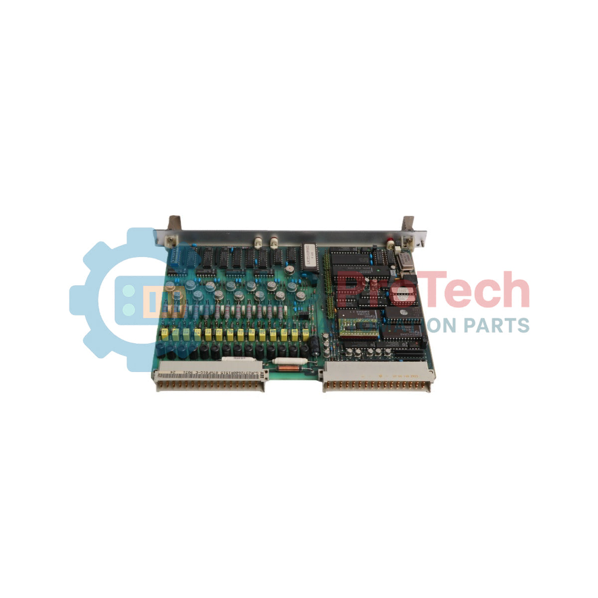
The ABB 88QT03C-E GJR2374500R2111 is a bus coupler module designed for signal processing and bus interfacing within the ABB (BBC) PROCONTROL P distributed control system. Operating on a 24 V DC power supply, this double-board module serves as a critical communication bridge between input/output stations and the central PROCONTROL system bus network.

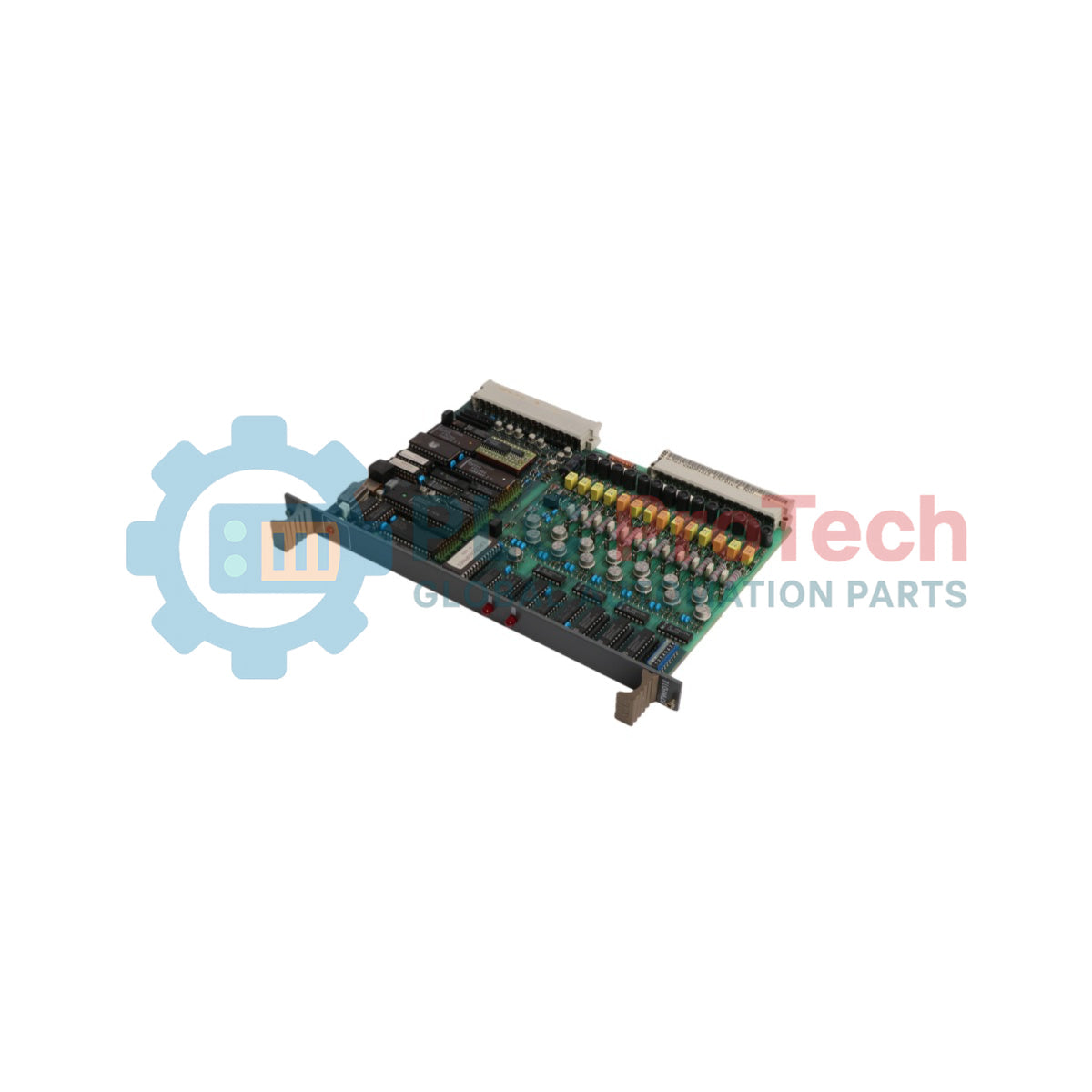
Built on a dual-printed circuit board architecture, the ABB 88QT03C-E GJR2374500R2111 handles high-speed data transmission and cycle-based signal exchange. The module features an onboard RS-485 interface operating at 1 MBaud to communicate with remote bus coupling hardware, supporting passive differential signal processing and dedicated cable connections for multi-cabinet layouts.

Designed for demanding power generation and industrial automation environments, the ABB 88QT03C-E GJR2374500R2111 incorporates cyclic firmware self-diagnostics. Internal monitoring functions include dual-microprocessor verification, parity bit data protection, station bus telegram sink time monitoring, and external disturbance signal logging to maintain uninterrupted control system availability.

Features

  • PROCONTROL P System Integration: Connects input/output stations directly to the station bus for cyclic data transmission and system diagnostics.
  • RS-485 Communication Port: Operates at 1 MBaud over RS-485 differential lines for reliable interconnectivity between coupling modules.
  • Integrated Diagnostic Architecture: Features dual-microprocessor mutual checking, parity bit protection, and automatic telegram sink time monitoring.
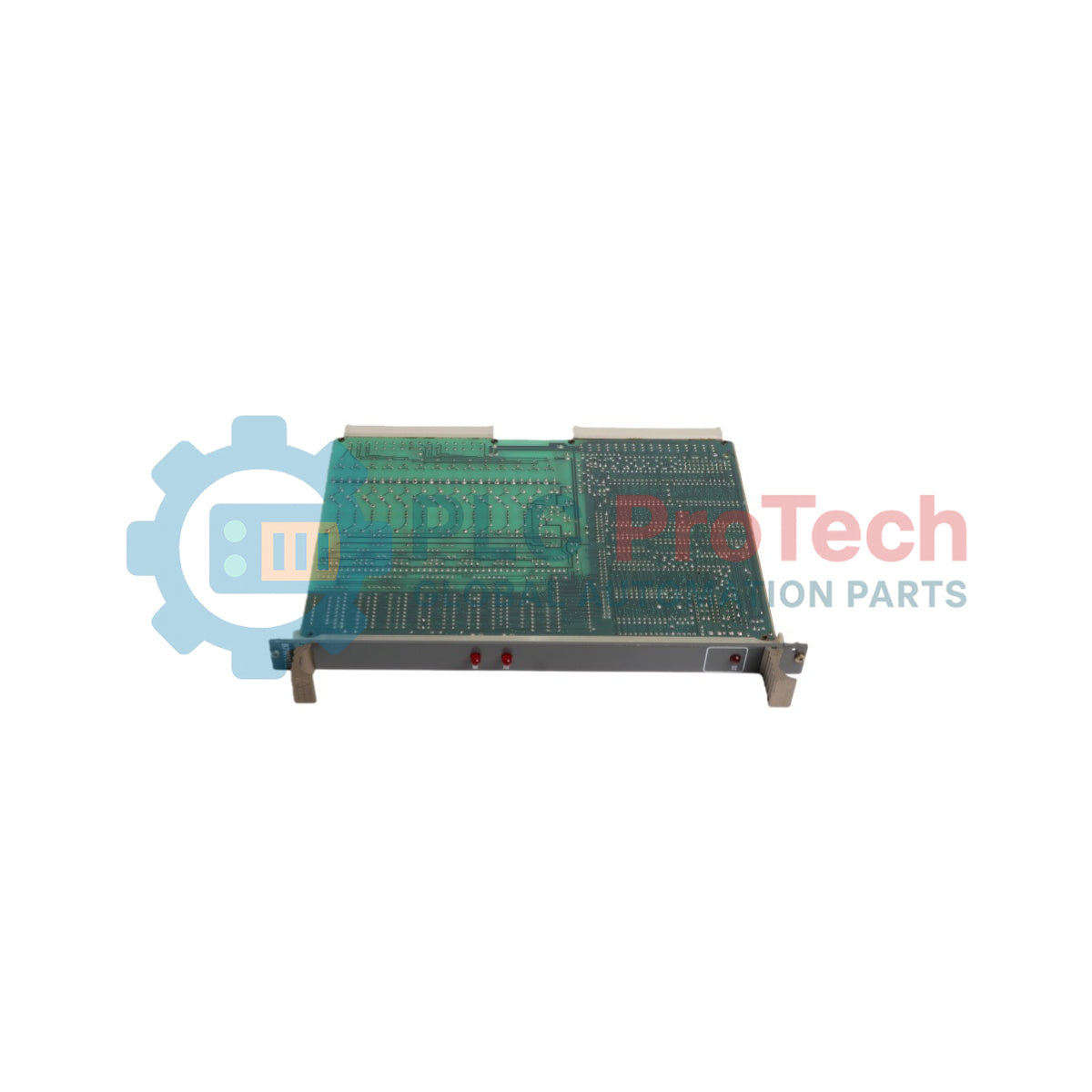
  • Front Panel LED Annunciation: Includes dedicated status indicators for general disturbance (ST), I/O station disturbance (STEA), simulation mode (SIM), and data transfer participation (EAVE).
  • Hardware Configuration Switches: Equipped with onboard DIP switches (S1) and jumpers to set output safety states, event processing response times, and cabinet wiring modes.

Applications

  • Power Plant Automation: Interfacing remote process I/O racks with central PROCONTROL P turbine and boiler control networks.
  • Industrial Distributed Control Systems (DCS): Coupling localized I/O station bus signals across multi-cabinet configurations.

Technical Specifications

General

Parameter Specification
Manufacturer ABB / BBC
Model Number 88QT03C-E
Part Number GJR2374500R2111
Product Type Bus Coupler Module
System Compatibility PROCONTROL P

Electrical

Parameter Specification
Operating Voltage 24 V DC +/- 25%
Current Consumption Approx. 166 mA
Power Dissipation 4 W (typical)
Disturbance Input Voltage (Ue) 24 V DC
Disturbance Input Current (Ie) 5 mA
Annunciation Output Voltage (Ua) 24 V DC
Annunciation Output Current (Ia) 6 mA

Communication

Parameter Specification
Communication Interface RS-485
Transmission Rate 1 MBaud
Termination Resistor 100 Ohm
Passive Differential Voltage 400 mV
Max. Inter-Module Connection 10 m (total) / 1 m via cable 89IK01

Environmental and Immunity

Parameter Specification
Electrostatic Discharge (ESD) 8 kV to front panel (acc. to IEC 801/2)
Electromagnetic Compatibility (EMC) 2 kV burst in remote bus cable (acc. to IEC 801/4)

Mechanical

Parameter Specification
Board Dimensions 6 units, 2 divisions, 160 mm deep
Board Construction 2 mechanically and electrically connected PCBs
Connector X11 48-pole edge connector type F (Station Bus / IO)
Connector X21 32-pole edge connector type F (External Disturbance)
Module Weight Approx. 0.83 kg

Connections / Interfaces

Interface Connector Type Function
Connector X11 48-Pole Edge Connector (Type F) Station bus communication and I/O station bus interface
Connector X21 32-Pole Edge Connector (Type F) External disturbance signals (SME1-SME3, SMS, STX)

Installation Guidelines

  1. Power Disconnection: Shut off 24 V DC power to the target PROCONTROL cabinet or subrack before inserting or removing the module.
  2. ESD Safety: Wear an anti-static wrist strap connected to cabinet earth ground during handling to protect electronic components.
  3. Jumper & DIP Switch Setup: Verify DIP switch S1 contact settings (for last-valid vs. zero value output on fault) and configuration jumpers before rack slot insertion.
  4. Card Insertion: Align the double board evenly with the subrack guide rails and push firmly until edge connectors X11 and X21 sit completely in the backplane sockets.
  5. Bus Cable Connection: Connect appropriate interface cables (such as 89IK01 or 89IK10) to their corresponding terminal blocks or bus isolator units (70BT01).

Configuration and Commissioning

  • EEPROM Initialization: Upon initial power-up, user parameters and address lists are transferred from EEPROM into main RAM via PDDS programming tools.
  • Diagnostic Verification: Monitor the front panel LEDs during startup: STEA flashing for ~4 seconds indicates RAM loading. Steady green EAVE indicates active participation in data transfer.

FAQ

What is the primary function of the ABB 88QT03C-E GJR2374500R2111 bus coupler module?

The ABB 88QT03C-E GJR2374500R2111 connects remote I/O stations to the central station bus within the PROCONTROL P distributed control system.

What are the power supply requirements for the ABB 88QT03C-E GJR2374500R2111?

The ABB 88QT03C-E GJR2374500R2111 operates on a nominal 24 V DC supply (+/- 25%) with a typical current consumption of 166 mA and 4 W power dissipation.

What connectors are used on the ABB 88QT03C-E GJR2374500R2111 module?

The module utilizes a 48-pole Type F edge connector (X11) for station bus and I/O bus connections, and a 32-pole Type F edge connector (X21) for external disturbance signals.

What do the front panel status LEDs indicate on the ABB 88QT03C-E GJR2374500R2111?

The ST LED signals general disturbances, STEA indicates I/O station fault or memory loading, SIM illuminates during output simulation, and EAVE confirms active data transfer.

View all FAQs →

Quantity
Shipping & Returns

Global Express Shipping

  • Standard Delivery: 4–6 business days via DHL, FedEx, and UPS.
  • Express Dispatch: Same-day dispatch for in-stock orders placed before 2:00 PM (GMT+8).
  • Worldwide Coverage: Serving over 150 countries.

Returns & Warranty

  • 30-Day Guarantee: Returns accepted for in-stock products in original, factory-sealed packaging.
  • 12-Month Warranty: Every industrial component is backed by our technical warranty.
Reviews
1 of 3
Only 4 item(s) left in stock
Quantity
View full details

Global Express Shipping

  • Standard Delivery: 4-6 Business Days via DHL, FedEx, and UPS.
  • Express Dispatch: Same-day dispatch for in-stock orders placed before 2:00 PM (GMT+8).
  • Worldwide Coverage: Serving over 150 countries, including rapid delivery to Saudi Arabia and UAE.

Returns & Warranty

  • 30-Day Guarantee: Returns accepted for in-stock products in original, factory-sealed packaging.
  • 12-Month Warranty: Every industrial component is backed by our professional technical warranty.

Orders are processed and delivered Monday-Friday (excluding public holidays).


For full eligibility, restocking fees, and international return details, please view our official Refund & Return Policy .

TECHNICAL SPECIFICATIONS

Color pattern
Dots
Country of origin
Switzerland
Power source
DC Power

Technical knowledge

IC693CPU360 vs IC693CPU364: Ethernet and Power Budget

Compare the IC693CPU360 and IC693CPU364 by Ethernet interface, +5 VDC load, memory, rack limits, and replacement checks.

1756-OF4 Output Wrong? Check Mode, RTB, and Scaling First

A field-first diagnostic sequence for 1756-OF4 analog output problems: channel mode, removable terminal block, scaling, and controlled electrical checks.

1746-OA8 vs 1746-OA16: Output Count and Current Limits

A direct comparison of 1746-OA8 and 1746-OA16 output count, common grouping, backplane current and temperature-derated load limits.

Replacing a 1761-NET-DNI: Capture These Settings First

A field checklist for recording the 1761-NET-DNI hardware series, firmware, EDS file, DF1 settings, DeviceNet address and messaging configuration before replacement.

EL3062 vs EL3062-0030: The Input Range Changes

The EL3062 is a 0–10 V EtherCAT terminal. The EL3062-0030 is a 0–30 V variant. This checklist covers identification, scaling and commissioning.

Replacing a 1769-OW8: Checks Before Moving Relay Loads

A field checklist for replacing Allen-Bradley 1769-OW8 relay output modules without losing load-group, wiring, and commissioning details.