


Replacing ABB DSQC 351: Controller and Network Checks
Checks to record before replacing ABB 3HNE 00006-1 DSQC 351: controller generation, X3/X5/X20/X21 wiring, DeviceNet settings, INTERBUS mapping, and LED states.
Manufacturer: Allen-Bradley
Product No.: 1794-TB3K
Country of origin:United States
Product Type: Conformal Coated Terminal Base Unit
Barcode: 8537101190
Payment: T/T, Western Union
Weight: 140g
Dimensions: 94 mm x 94 mm x 69 mm
Shipping port: Xiamen
Warranty: 12 months
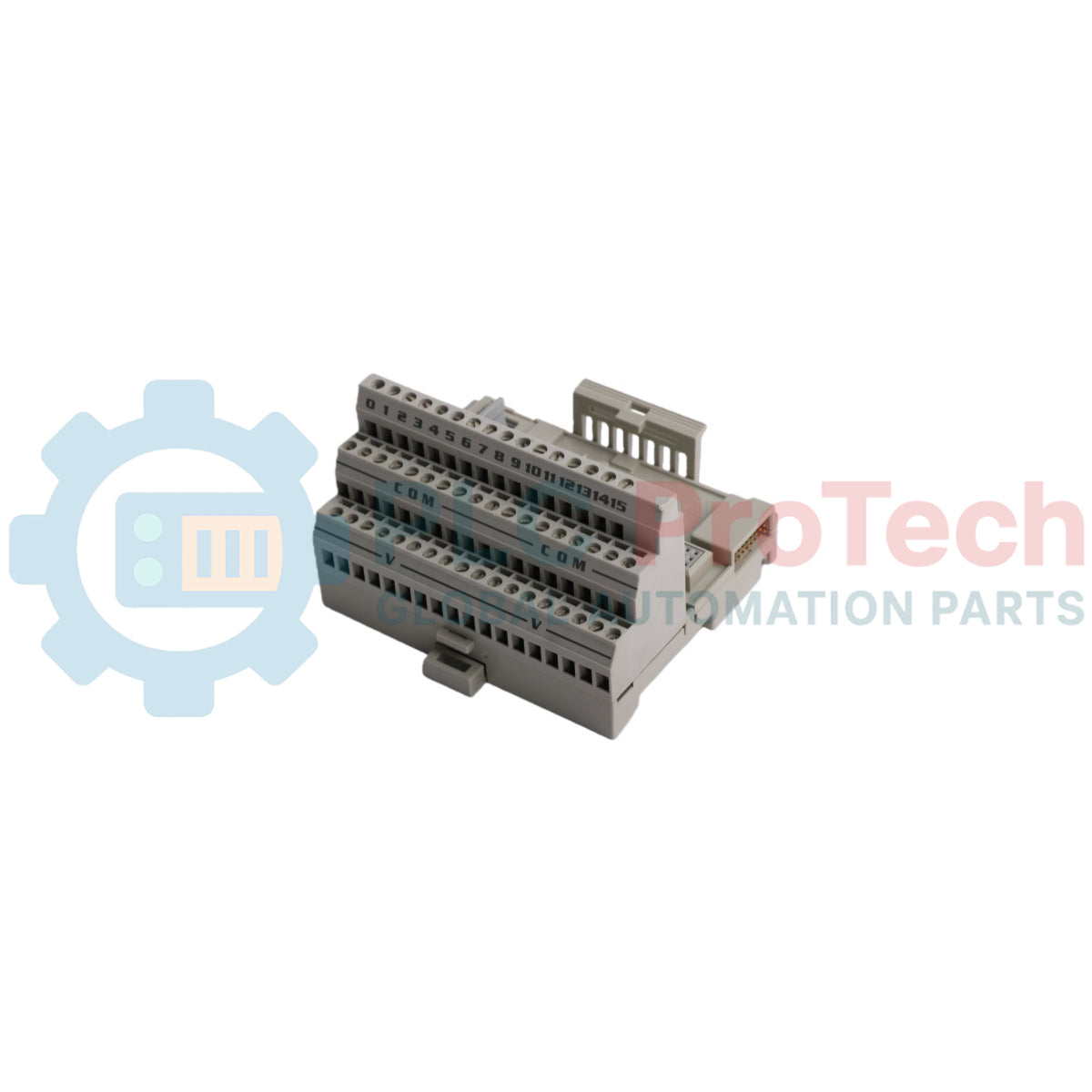
The 1794-TB3K is a specialized, ruggedized mounting and wiring component designed for the FLEX I/O distributed modular platform. This industrial hardware component forms the essential baseline configuration for remote I/O terminal assemblies, combining field-side sensor/actuator wiring points with an integrated backplane bus matrix. This specific variant features factory-applied conformal coating protection, which shields internal circuitry from corrosive atmospheric agents, humidity, and airborne contaminants often encountered in harsh operating areas.
Equipped with a three-tier terminal block configuration, the unit provides thirty-six individual termination screws to manage discrete or analog signals, power distribution paths, and common ground lines separately. The 1794-TB3K establishes backplane structural links via an integrated male/female FlexBus connector side-assembly, enabling continuous data and power transfer across the complete local modular cluster. It is standard in heavy-duty processing industries—such as wastewater treatment plants, offshore drilling platforms, pulp and paper processing plants, and chemical synthesis installations—requiring resilience against ambient environmental degradation.
| Parameter | Specification |
|---|---|
| Manufacturer | Rockwell Automation / Allen-Bradley |
| Brand | FLEX I/O |
| Part Number | 1794-TB3K |
| Component Type | Conformal Coated Terminal Base Unit |
| Termination Type | 3-Tier Screw Clamp Terminals |
| Number of Terminal Points | 36 |
| Wire Size Capacity | 0.34 mm2 to 2.5 mm2 (22 to 12 AWG) solid or stranded copper wire |
| Terminal Screw Torque | 0.56 to 0.79 N-m (5.0 to 7.0 lb-in) |
| Voltage Rating | 31.2V DC / 132V AC maximum |
| Current Capacity | 10 A maximum per power bus, 2 A maximum per signal terminal |
| Protection Type | Conformal coated circuit board substrate |
| Operating Temperature | 0 to 55 degC |
| Storage Temperature | -40 to 85 degC |
| Relative Humidity | 5% to 95% non-condensing |
| Country of Origin | USA |
| Weight | 0.14 kg |
| Dimensions | 94 mm x 94 mm x 69 mm |
| Terminal Row Designation | Function / Termination Allocation |
|---|---|
| Row A (Top Tier) | Input / Output signal wire connection nodes 0 through 15 |
| Row B (Middle Tier) | Sourcing power supply voltage distribution terminals (+V) |
| Row C (Bottom Tier) | Common signal reference return and chassis grounding links (COM/GND) |
Catch the upper rear mounting claws of the assembly block onto the top edge of a standard zinc-plated 35 mm DIN rail. Press down and inward firmly on the lower edge of the enclosure until the spring-loaded metallic retaining clip snaps over the bottom track rail.
Align the side-facing male FlexBus pins of the new unit with the matching female socket of the existing module or network adapter on the rail. Slide the base laterally until the two housings mate flush and the interlocking retention clips engage.
Strip the insulation from the incoming field conductors to a length of approximately 7 mm. Insert the bare copper wire fully into the designated screw clamp receptacle and tighten the terminal screw to a torque rating between 0.56 and 0.79 N-m.
Keep the protective cover plates over the FlexBus interface connections if adjacent slots on the DIN rail remain unpopulated. Avoid scratching the interior base board during cleaning or module replacement to prevent damaging the factory conformal coating film layer.
What distinguishes this base unit from a standard 1794-TB3 model?
This unit features a factory-applied conformal coating layer on its internal circuit board components to provide extra protection against harsh environmental contaminants.
Can this unit be mixed with non-conformal coated modules on the same rail?
Yes, it is physically and electrically compatible with standard modules, though the complete system should be coated to achieve full environmental resilience.
What wire gauge range can the terminal screws safely accommodate?
The terminal blocks accept solid or stranded copper conductors ranging from 22 AWG up to 12 AWG.
Does this component support the hot-swapping of operational I/O modules?
Yes, it allows electronic application modules to be removed and inserted under power without requiring the removal of field wires or shutting down the bus adapter.
Is an external power supply run directly to this terminal block?
Yes, field-side sensor and actuator supply voltage must be wired to the Row B terminals to distribute power across the module points.
What is the maximum current limit permitted per signal terminal?
Each independent signal terminal screw is rated to handle a continuous current flow of up to 2 A.
How does the unit connect to the main system programmable logic controller?
It links back to the main controller through a communications adapter module positioned at the leftmost position of the local DIN rail track.
Can this unit handle alternating current field instrumentation loops?
Yes, the electrical insulation design allows for switching signals up to a maximum rating of 132V AC.
What tools are required to mount the base onto the DIN rail?
No tools are required for mounting, as the unit snaps directly onto the rail, but a flat-head screwdriver can be used to release the lower latch during removal.
What is the maximum torque recommendation for the terminal clamp screws?
The screws should be tightened to a value within the 0.56 to 0.79 N-m range to prevent stripping while maintaining low contact resistance.


Global Express Shipping
Returns & Warranty


| Product Image | Model Number / Title | Condition | Availability | Action |
|---|---|---|---|---|

|
Allen-Bradley 1794-OB16P FLEX I/O Digital DC Output Module | Original New | In Stock | View Details |
Global Express Shipping
Returns & Warranty
Orders are processed and delivered Monday-Friday (excluding public holidays).
For full eligibility, restocking fees, and international return details, please view our official Refund & Return Policy .
| Color pattern |
Greyish White
|
| Country of origin |
United States
|
| Power source |
AC-powered
DC Power
|

Checks to record before replacing ABB 3HNE 00006-1 DSQC 351: controller generation, X3/X5/X20/X21 wiring, DeviceNet settings, INTERBUS mapping, and LED states.

Compare the IC693CPU360 and IC693CPU364 by Ethernet interface, +5 VDC load, memory, rack limits, and replacement checks.

A field-first diagnostic sequence for 1756-OF4 analog output problems: channel mode, removable terminal block, scaling, and controlled electrical checks.

A direct comparison of 1746-OA8 and 1746-OA16 output count, common grouping, backplane current and temperature-derated load limits.

A field checklist for recording the 1761-NET-DNI hardware series, firmware, EDS file, DF1 settings, DeviceNet address and messaging configuration before replacement.

The EL3062 is a 0–10 V EtherCAT terminal. The EL3062-0030 is a 0–30 V variant. This checklist covers identification, scaling and commissioning.