


Implementing 3-Switch XOR Ladder Logic with Internal Bit
Implement a 3-SPST switch XOR light circuit in LogixPro or RSLogix 500 using an internal relay bit. Includes truth tables, boolean equations, and verified.
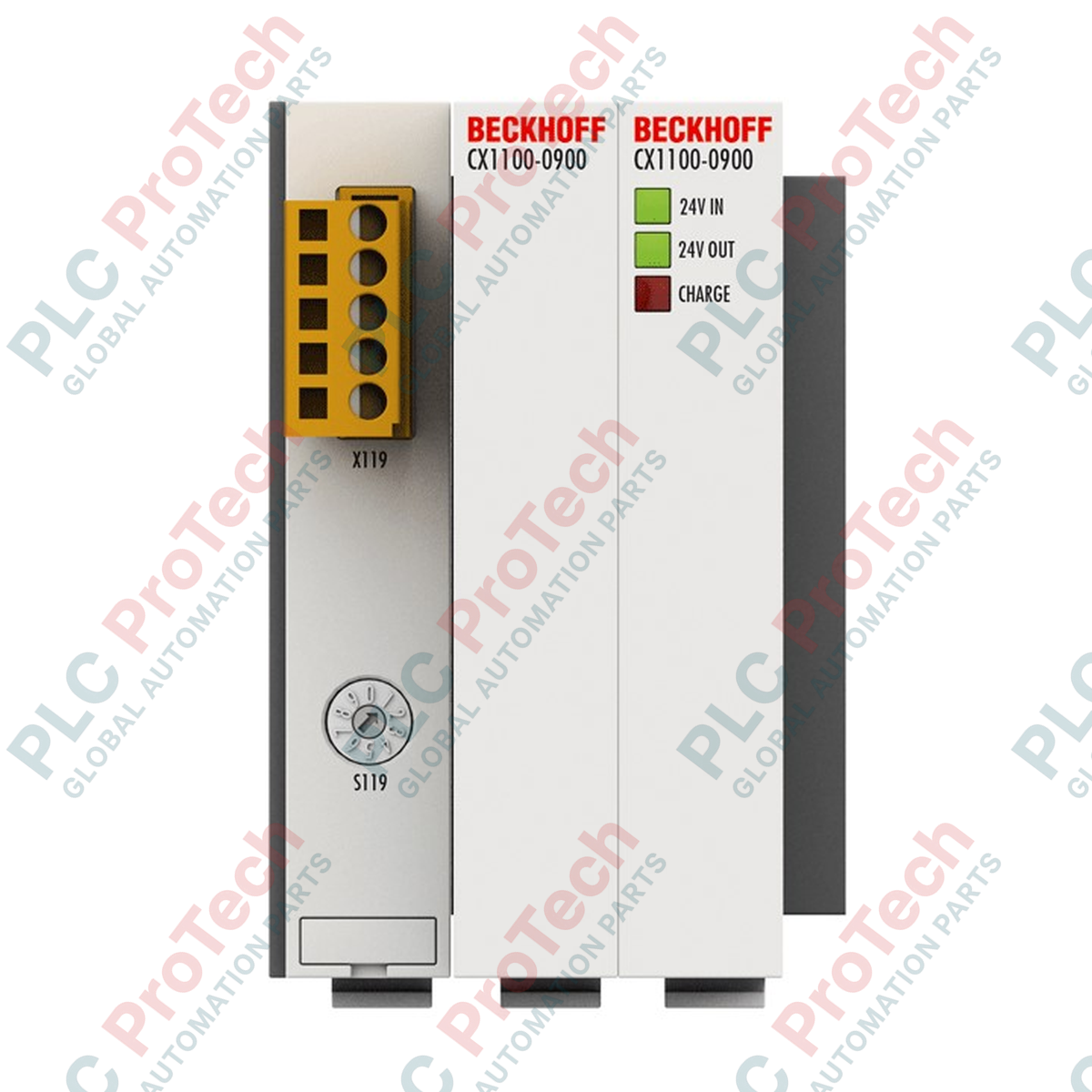
Designed to provide reliable short-term backup power for Embedded PCs, the Beckhoff CX1100-0900 utilizes capacitive storage technology to safeguard critical system data during sudden power interruptions. By interfacing directly with the host controller via the internal PC/104 system bus, this module enables maintenance-free protection without the degradation risks associated with traditional battery-backed systems. The unit serves as a dependable buffer, allowing the PLC application to write active process states and retain variables directly to persistent memory before a complete system shutdown.
| Parameter | Specification |
|---|---|
| Manufacturer | Beckhoff Automation |
| Model | CX1100-0900 |
| Series | CX Series (CX1000, CX1010, CX1020, CX1030) |
| Input Power Supply | 24 V DC (-15% / +20%) |
| Storage Technology | Capacitive (Double-layer capacitors) |
| Capacity | 20 As (Ampere-seconds) |
| Retention Time | Adjustable, load-dependent |
| Maximum Output Current | 550 mA (24 V DC) |
| Charging Current | Max. 4 A |
| Interface to CPU | 16-bit ISA (PC/104 standard) |
| Diagnostics | LEDs for 24 V DC Input, 24 V DC Output, and Charge |
| Maximum Power Loss | 2 W |
| Protection Rating | IP20 |
| Operating Temperature | 0 to 55 degC |
| Storage Temperature | -25 to 85 degC |
| Relative Humidity | 95%, non-condensing |
| Vibration/Shock Resistance | Conforms to EN 60068-2-6 / EN 60068-2-27 |
| EMC Immunity/Emission | Conforms to EN 61000-6-2 / EN 61000-6-4 |
| Dimensions (W x H x D) | 57 mm x 100 mm x 91 mm |
| Net Weight | 346 g |
| Shipping Weight (Calculated) | 2.0 kg |
The CX1100-0900 belongs strictly to the first-generation CX control family (CX1000, CX1010, CX1020, CX1030). It is connected directly via the standard 16-bit PC/104 system bus on the left side of the CPU. This module is physically incompatible with newer Beckhoff Embedded PC series, such as the CX2000 or CX5100, which rely on PCIe-based bus extensions. For system migrations, verify that the existing PLC code utilizes the legacy TwinCAT system libraries rather than modern unified-UPS functions.
Capacitive modules are designed for high-density, ultra-short-term backup applications. A total capacity of 20 As means that at the maximum rated current draw of 550 mA, the module can sustain power for approximately 36 seconds. This duration is strictly intended to execute write-to-disk or write-to-NOVRAM routines. It must not be treated as a continuous operational power supply. Thermal control is critical: operating continuously near the 55 degC limit accelerated the natural aging profile of internal double-layer capacitors, reducing actual hold-up performance over time.
Upon initial installation, the internal capacitors require a brief charging phase. If the charge LED is flashing or off, the module will not support full system ride-through during a power dip. Ensure your TwinCAT PLC project implements the FB_S_UPS function block. This block must be configured with the specific parameters of the CX1100-0900 to ensure that the persistent data-saving task is given execution priority immediately when the power supply status transitions from normal to battery/backup mode.
CRITICAL WARNING:
Ensure all upstream power supplies are fully de-energized and locked out before attempting to physically couple or uncouple the CX1100-0900 module. Electrostatic and capacitive charges can remain active within the internal system bus. Failure to comply can result in damage to the PC/104 connector pins and processor instability.
Mount the module onto a standard 35 mm DIN rail (EN 60715) immediately to the left of the CPU module, ensuring proper spatial alignment with the bus connectors.
Slide the module laterally along the DIN rail until the 16-bit ISA PC/104 system bus connector plugs firmly and flush into the mating slot of the adjacent CX CPU module.
Engage the integrated mechanical locking mechanism to prevent axial shifting or separation of the bus contacts during operation under high vibration.
Apply 24 V DC system power and observe the Diagnostic LEDs. Confirm the 'Charge' LED illuminates, indicating normal initialization and capacitive cell charging.
Global Express Shipping
Returns & Warranty


Manufacturer: BECKHOFF
Product No.: CX1100-0900
Country of origin:Germany
Product Type: PLC UPS Modules
Payment: T/T, Western Union
Weight: 500g
Dimensions: 57 mm x 100 mm x 91 mm
Shipping port: Xiamen
Warranty: 12 months
Designed to provide reliable short-term backup power for Embedded PCs, the Beckhoff CX1100-0900 utilizes capacitive storage technology to safeguard critical system data during sudden power interruptions. By interfacing directly with the host controller via the internal PC/104 system bus, this module enables maintenance-free protection without the degradation risks associated with traditional battery-backed systems. The unit serves as a dependable buffer, allowing the PLC application to write active process states and retain variables directly to persistent memory before a complete system shutdown.
| Parameter | Specification |
|---|---|
| Manufacturer | Beckhoff Automation |
| Model | CX1100-0900 |
| Series | CX Series (CX1000, CX1010, CX1020, CX1030) |
| Input Power Supply | 24 V DC (-15% / +20%) |
| Storage Technology | Capacitive (Double-layer capacitors) |
| Capacity | 20 As (Ampere-seconds) |
| Retention Time | Adjustable, load-dependent |
| Maximum Output Current | 550 mA (24 V DC) |
| Charging Current | Max. 4 A |
| Interface to CPU | 16-bit ISA (PC/104 standard) |
| Diagnostics | LEDs for 24 V DC Input, 24 V DC Output, and Charge |
| Maximum Power Loss | 2 W |
| Protection Rating | IP20 |
| Operating Temperature | 0 to 55 degC |
| Storage Temperature | -25 to 85 degC |
| Relative Humidity | 95%, non-condensing |
| Vibration/Shock Resistance | Conforms to EN 60068-2-6 / EN 60068-2-27 |
| EMC Immunity/Emission | Conforms to EN 61000-6-2 / EN 61000-6-4 |
| Dimensions (W x H x D) | 57 mm x 100 mm x 91 mm |
| Net Weight | 346 g |
| Shipping Weight (Calculated) | 2.0 kg |
The CX1100-0900 belongs strictly to the first-generation CX control family (CX1000, CX1010, CX1020, CX1030). It is connected directly via the standard 16-bit PC/104 system bus on the left side of the CPU. This module is physically incompatible with newer Beckhoff Embedded PC series, such as the CX2000 or CX5100, which rely on PCIe-based bus extensions. For system migrations, verify that the existing PLC code utilizes the legacy TwinCAT system libraries rather than modern unified-UPS functions.
Capacitive modules are designed for high-density, ultra-short-term backup applications. A total capacity of 20 As means that at the maximum rated current draw of 550 mA, the module can sustain power for approximately 36 seconds. This duration is strictly intended to execute write-to-disk or write-to-NOVRAM routines. It must not be treated as a continuous operational power supply. Thermal control is critical: operating continuously near the 55 degC limit accelerated the natural aging profile of internal double-layer capacitors, reducing actual hold-up performance over time.
Upon initial installation, the internal capacitors require a brief charging phase. If the charge LED is flashing or off, the module will not support full system ride-through during a power dip. Ensure your TwinCAT PLC project implements the FB_S_UPS function block. This block must be configured with the specific parameters of the CX1100-0900 to ensure that the persistent data-saving task is given execution priority immediately when the power supply status transitions from normal to battery/backup mode.
CRITICAL WARNING:
Ensure all upstream power supplies are fully de-energized and locked out before attempting to physically couple or uncouple the CX1100-0900 module. Electrostatic and capacitive charges can remain active within the internal system bus. Failure to comply can result in damage to the PC/104 connector pins and processor instability.
Mount the module onto a standard 35 mm DIN rail (EN 60715) immediately to the left of the CPU module, ensuring proper spatial alignment with the bus connectors.
Slide the module laterally along the DIN rail until the 16-bit ISA PC/104 system bus connector plugs firmly and flush into the mating slot of the adjacent CX CPU module.
Engage the integrated mechanical locking mechanism to prevent axial shifting or separation of the bus contacts during operation under high vibration.
Apply 24 V DC system power and observe the Diagnostic LEDs. Confirm the 'Charge' LED illuminates, indicating normal initialization and capacitive cell charging.
Global Express Shipping
Returns & Warranty
Orders are processed and delivered Monday-Friday (excluding public holidays).
For full eligibility, restocking fees, and international return details, please view our official Refund & Return Policy .
| Country of origin |
Germany
|

Implement a 3-SPST switch XOR light circuit in LogixPro or RSLogix 500 using an internal relay bit. Includes truth tables, boolean equations, and verified.

Integrate Allen-Bradley CompactLogix, Caterpillar ATS, and generators into DeltaV DCS over Modbus RTU. Covers ProSoft MVI69-MCM, Miille DIN266 gateways.

ONS instruction fires but the OTE coil never latches in Studio 5000 because the one-shot is only true for one scan. Use OTL/OTU or seal-in logic instead.

Configure Allen-Bradley Kinetix 5500 servo drives on EtherNet/IP. Covers CIP Sync, IEEE 1588 V2 timing, Stratix selection, DLR topology, and HMI.

A moving-average filter is the sliding-window smoother most instrument engineers drop into DCS and PLC analog paths. Here is how the window works, how N and sample time set lag, and when a...

On Frame 5–9 gas turbines, GE Mark VI and Mark VIe run control as function-block application software. This article maps process, protection, and sequencing functions—and what Toolbox ST access...