


Implementing 3-Switch XOR Ladder Logic with Internal Bit
Implement a 3-SPST switch XOR light circuit in LogixPro or RSLogix 500 using an internal relay bit. Includes truth tables, boolean equations, and verified.

Designed for direct field deployment in decentralized architectures, the Beckhoff EPP5101-1002 provides a high-performance interface for incremental encoders using RS422 differential or TTL single-ended signals. This robust IP67-rated module is part of the EtherCAT P system, merging high-speed communication and power delivery into a single, unified cable. By processing differential signals (A, B, C) directly on the machine, the module eliminates long analog wiring runs and significantly reduces electromagnetic interference (EMI) risks in demanding industrial installations.
| Parameter | Value |
|---|---|
| Manufacturer | Beckhoff |
| Model Number | EPP5101-1002 |
| Protocol | EtherCAT |
| Bus Interface | 2 x M8 socket, shielded, screw type, P-coded |
| Connection Technology | M12, 8-pin, screw type (A-coded) |
| Number of Channels | 1 |
| Encoder Signals | A, A (inv), B, B (inv), C, C (inv) differential inputs |
| Encoder Operating Voltage | 24 V DC / 0.5 A (derived from Us supply) |
| Nominal Voltage | 24 V DC (-15% / +20%) |
| Counter Capacity | 16 or 32 bit, binary |
| Limit Frequency | 1 MHz (4 million increments/s with 4-fold evaluation) |
| Current Consumption (Us) | Typically 100 mA |
| Electrical Isolation | 500 V RMS |
| Operating Temperature | 0 to 55 degC |
| Storage Temperature | -25 to 85 degC |
| Protection Class | IP65/66/67 (conforms to EN 60529) |
| Country of Origin | Germany |
| Shipping Weight (Calculated) | 0.5 kg |
| Package Dimensions (Calculated) | 150 x 50 x 50 mm |
| M12 Pin | Signal Assignment | Function |
|---|---|---|
| 1 | A | Encoder Channel A (Non-inverted Input) |
| 2 | A (inv) | Encoder Channel A (Inverted Input) |
| 3 | B | Encoder Channel B (Non-inverted Input) |
| 4 | B (inv) | Encoder Channel B (Inverted Input) |
| 5 | C / Zero | Latch/Zero-Pulse Input (Non-inverted) |
| 6 | C (inv) | Latch/Zero-Pulse Input (Inverted) |
| 7 | GND | Reference Ground for Encoder Power |
| 8 | +24 V DC | Auxiliary Encoder Sensor Supply Output |
The EPP5101-1002 is specifically built for EtherCAT P (P-coded physical interface). Note that it cannot be plugged directly into standard EtherCAT (EP5101-0002) networks without the use of an EP9224 or EP9214 junction box, which breaks out communication and the respective Us/Up power lines. TwinCAT 3 requires standard ESI file updates to correctly recognize the EPP series hardware versions.
When configuring downstream EtherCAT P nodes, verify that the total cumulative current drawn from the Us (system/sensor power) loop does not exceed the line thresholds. High-resolution, multi-channel linear encoders can cause significant voltage drops across long M8 P-coded link lines, triggering under-voltage fault codes in TwinCAT.
To ensure stable 1 MHz count operations, utilize double-shielded twisted-pair cabling for all differential M12 encoder runs. Standard single-ended TTL encoders are more susceptible to ambient motor-drive noise; hence, we highly recommend terminating the cable shield completely 360 degrees around the metallic M12 plug shell.
CRITICAL WARNING:
Isolate all electrical power sources before handling, installing, or servicing EtherCAT P physical connectors. Ensure the field cables are not under load during coupling to prevent arcing and connector degradation on the sensitive P-coded gold pins.
Mount the module on a flat machine surface using standard M3 screws. Ground the mounting tabs directly to the frame to ensure maximum EMI immunity.
Connect the incoming EtherCAT P M8 cable to the P-coded input socket, hand-tightening to IP67 specifications (typically 0.4 Nm torque).
Install the M12 encoder interface cable to the bottom connection port. Protect any unused M8 or M12 interfaces with industrial plastic dust caps to preserve the IP67 housing seal integrity.
Global Express Shipping
Returns & Warranty


Manufacturer: BECKHOFF
Product No.: EPP5101-1002
Country of origin:Germany
Product Type: EtherCAT I/O Modules
Payment: T/T, Western Union
Weight: 500g
Dimensions: 150 x 50 x 50 mm
Shipping port: Xiamen
Warranty: 12 months
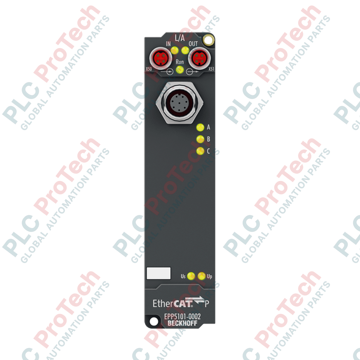
Designed for direct field deployment in decentralized architectures, the Beckhoff EPP5101-1002 provides a high-performance interface for incremental encoders using RS422 differential or TTL single-ended signals. This robust IP67-rated module is part of the EtherCAT P system, merging high-speed communication and power delivery into a single, unified cable. By processing differential signals (A, B, C) directly on the machine, the module eliminates long analog wiring runs and significantly reduces electromagnetic interference (EMI) risks in demanding industrial installations.
| Parameter | Value |
|---|---|
| Manufacturer | Beckhoff |
| Model Number | EPP5101-1002 |
| Protocol | EtherCAT |
| Bus Interface | 2 x M8 socket, shielded, screw type, P-coded |
| Connection Technology | M12, 8-pin, screw type (A-coded) |
| Number of Channels | 1 |
| Encoder Signals | A, A (inv), B, B (inv), C, C (inv) differential inputs |
| Encoder Operating Voltage | 24 V DC / 0.5 A (derived from Us supply) |
| Nominal Voltage | 24 V DC (-15% / +20%) |
| Counter Capacity | 16 or 32 bit, binary |
| Limit Frequency | 1 MHz (4 million increments/s with 4-fold evaluation) |
| Current Consumption (Us) | Typically 100 mA |
| Electrical Isolation | 500 V RMS |
| Operating Temperature | 0 to 55 degC |
| Storage Temperature | -25 to 85 degC |
| Protection Class | IP65/66/67 (conforms to EN 60529) |
| Country of Origin | Germany |
| Shipping Weight (Calculated) | 0.5 kg |
| Package Dimensions (Calculated) | 150 x 50 x 50 mm |
| M12 Pin | Signal Assignment | Function |
|---|---|---|
| 1 | A | Encoder Channel A (Non-inverted Input) |
| 2 | A (inv) | Encoder Channel A (Inverted Input) |
| 3 | B | Encoder Channel B (Non-inverted Input) |
| 4 | B (inv) | Encoder Channel B (Inverted Input) |
| 5 | C / Zero | Latch/Zero-Pulse Input (Non-inverted) |
| 6 | C (inv) | Latch/Zero-Pulse Input (Inverted) |
| 7 | GND | Reference Ground for Encoder Power |
| 8 | +24 V DC | Auxiliary Encoder Sensor Supply Output |
The EPP5101-1002 is specifically built for EtherCAT P (P-coded physical interface). Note that it cannot be plugged directly into standard EtherCAT (EP5101-0002) networks without the use of an EP9224 or EP9214 junction box, which breaks out communication and the respective Us/Up power lines. TwinCAT 3 requires standard ESI file updates to correctly recognize the EPP series hardware versions.
When configuring downstream EtherCAT P nodes, verify that the total cumulative current drawn from the Us (system/sensor power) loop does not exceed the line thresholds. High-resolution, multi-channel linear encoders can cause significant voltage drops across long M8 P-coded link lines, triggering under-voltage fault codes in TwinCAT.
To ensure stable 1 MHz count operations, utilize double-shielded twisted-pair cabling for all differential M12 encoder runs. Standard single-ended TTL encoders are more susceptible to ambient motor-drive noise; hence, we highly recommend terminating the cable shield completely 360 degrees around the metallic M12 plug shell.
CRITICAL WARNING:
Isolate all electrical power sources before handling, installing, or servicing EtherCAT P physical connectors. Ensure the field cables are not under load during coupling to prevent arcing and connector degradation on the sensitive P-coded gold pins.
Mount the module on a flat machine surface using standard M3 screws. Ground the mounting tabs directly to the frame to ensure maximum EMI immunity.
Connect the incoming EtherCAT P M8 cable to the P-coded input socket, hand-tightening to IP67 specifications (typically 0.4 Nm torque).
Install the M12 encoder interface cable to the bottom connection port. Protect any unused M8 or M12 interfaces with industrial plastic dust caps to preserve the IP67 housing seal integrity.
Global Express Shipping
Returns & Warranty
Orders are processed and delivered Monday-Friday (excluding public holidays).
For full eligibility, restocking fees, and international return details, please view our official Refund & Return Policy .
| Country of origin |
Germany
|

Implement a 3-SPST switch XOR light circuit in LogixPro or RSLogix 500 using an internal relay bit. Includes truth tables, boolean equations, and verified.

Integrate Allen-Bradley CompactLogix, Caterpillar ATS, and generators into DeltaV DCS over Modbus RTU. Covers ProSoft MVI69-MCM, Miille DIN266 gateways.

ONS instruction fires but the OTE coil never latches in Studio 5000 because the one-shot is only true for one scan. Use OTL/OTU or seal-in logic instead.

Configure Allen-Bradley Kinetix 5500 servo drives on EtherNet/IP. Covers CIP Sync, IEEE 1588 V2 timing, Stratix selection, DLR topology, and HMI.

A moving-average filter is the sliding-window smoother most instrument engineers drop into DCS and PLC analog paths. Here is how the window works, how N and sample time set lag, and when a...

On Frame 5–9 gas turbines, GE Mark VI and Mark VIe run control as function-block application software. This article maps process, protection, and sequencing functions—and what Toolbox ST access...