BECKHOFF

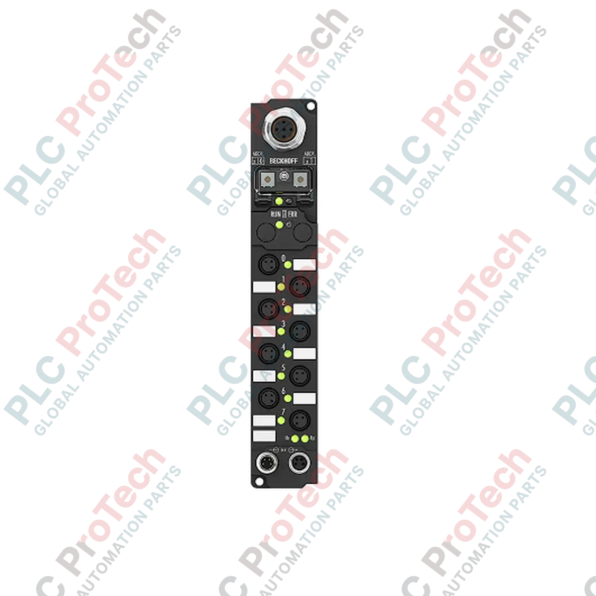
Beckhoff IP2020-B730 Fieldbus Box Modbus Digital Output Module

SKU IP2020-B730

In stock
  • 12-month warranty
  • Free returns within 30 days
  • Manufacturer: BECKHOFF
  • Product No.: IP2020-B730
  • Origin Germany
  • Product Type: Fieldbus Box Modules
  • Payment: T/T, Western Union
  • Weight: 1.0 kg
  • Dimensions: 30 mm x 175 mm x 26.5 mm
  • Shipping port: Xiamen
  • Warranty: 12 months

Tags

Quantity

Product Description

Description

Decentralized actuation on the factory floor is directly managed by the Beckhoff IP2020-B730, an integrated Modbus RTU/ASCII fieldbus module carrying 8 digital output channels. This ruggedized fieldbus device enables direct wiring of actuators outside of traditional electrical enclosures, communicating seamlessly over serial RS485 lines. Featuring a robust polyamide housing and IP67-rated construction, the module simplifies field-level wiring through standard industrial connectors while maintaining high electrical isolation between control logic and fieldbus components.

Features

  • 8 Digital Outputs: Standard 8 mm snap-type connections for simplified field integration.
  • Serial Protocol Compatibility: Native support for Modbus RTU and Modbus ASCII protocols.
  • High Current Capacity: Delivers up to 2 A per channel with an aggregate sum limit of 4 A.
  • Integrated Diagnostics: Local LED status indicators for real-time fieldbus communication and channel state tracking.
  • Addressing Utility: Easy network configuration using integrated manual address selection switches or KS2000 software.

Applications

  • Machine-mount control systems requiring direct actuator connections without control cabinets.
  • Conveyor and material handling lines utilizing distributed serial fieldbus architectures.
  • Harsh manufacturing environments demanding IP65/66/67 physical protection.

Technical Specifications

Parameter Specification
Manufacturer Beckhoff
Model Number IP2020-B730
Fieldbus Protocol Modbus RTU / Modbus ASCII
Physical Layer / Medium RS485 (Screened, twisted copper cable 2 x 0.25 mm²)
Data Transfer Rates 150, 300, 600, 1200, 2400, 4800, 9600, 19200, 38400 baud
Number of Outputs 8 digital outputs
Output Type / Connection 8 mm, snap-on type socket
Nominal Output Voltage 24 V DC (-15% / +20%)
Max. Output Current 2 A per channel (short-circuit proof), 4 A total sum limit
Bus Interface Connection 1 x M12 socket, 5-pin, B-coded
Power Supply Port (Feed) 1 x M8 male connector, 4-pin
Power Supply Port (Downstream) 1 x M8 female connector, 4-pin
Electrical Isolation Control voltage to fieldbus: Yes
Operating Temperature 0 to +55 degC
Storage Temperature -25 to +85 degC
Ingress Protection Rating IP65 / IP66 / IP67 (conforms to EN 60529)
Housing Material PA6 (Polyamide)
Dimensions (W x H x D) 30 mm x 175 mm x 26.5 mm
Unit Weight 210 g

Connections and Interfaces

Interface Type Connector Pinout Assignment / Function
M8 Power Feed (Male) Pin 1 Feed Control Voltage Us (+24 V DC)
Pin 2 Feed Load Voltage Up (+24 V DC)
Pin 3 GNDs (Control Voltage Ground)
Pin 4 GNDp (Load Voltage Ground)
M12 Bus Interface (B-coded) Pin 2 TxD/RxD-N (A-line, RS485)
Pin 4 TxD/RxD-P (B-line, RS485)
Pin 5 Shield / Ground

Alternative Models & Compatibility

The IP2020-B730 belongs to the legacy serial Fieldbus Box family. For newer EtherCAT topologies, migrate toward the Beckhoff EP series modules. Ensure your host PLC contains the appropriate Modbus RTU serial communication master card or gateway device supporting baud speeds matching this module's DIP switch settings.

Application Pitfalls & Engineering Notes

While individual channels support up to 2 A, the total sum limit across all 8 outputs must not exceed 4 A. If multiple inductive or high-current loads are triggered simultaneously, ensure that external power budgeting is calculated to prevent internal thermal overload. Highly cyclic inductive loads require external suppression snubber networks to prolong the internal switching contact life expectancy.

Commissioning & Wiring Tips

Avoid using non-shielded RS485 lines over long runs. Always verify that a 120-Ohm termination resistor is present on the physical end-of-line RS485 node to protect Modbus data packets from line reflection errors. Device node addressing can be quickly adjusted using the two rotary switches beneath the protective IP67 seal cover.

Installation Guidelines

CRITICAL WARNING:

De-energize all power lines feeding the module before commencing installation. Failure to disconnect the 24 V DC control (Us) and load (Up) supply lines can lead to equipment short-circuits, interface damage, or electrical hazards for field operators.

1

Mount the physical module to the machine bed or bracket using two M3 screws through the 3.5 mm diameter mounting holes.

2

Set the physical Modbus station node address utilizing the manual rotary selectors under the protective housing screw-cap.

3

Connect the B-coded M12 bus cabling, securing the locking sleeve to ensure proper IP67 environmental sealing.

4

Attach the M8 power cables, then engage the 24 V DC power sources to commission the bus communications.

Shipping & Returns

Global Express Shipping

  • Standard Delivery: 4–6 business days via DHL, FedEx, and UPS.
  • Express Dispatch: Same-day dispatch for in-stock orders placed before 2:00 PM (GMT+8).
  • Worldwide Coverage: Serving over 150 countries.

Returns & Warranty

  • 30-Day Guarantee: Returns accepted for in-stock products in original, factory-sealed packaging.
  • 12-Month Warranty: Every industrial component is backed by our technical warranty.
FAQ
What is the collective output current limit for the IP2020-B730?
The module permits a maximum of 2 A per individual digital output channel; however, the cumulative load current across all eight active channels must not exceed 4 A simultaneously.
Which fieldbus protocols are natively supported by this module?
The IP2020-B730 supports Modbus RTU and Modbus ASCII serial protocols over a physical RS485 communication link.
How do you set the serial node address on the IP2020-B730?
The network address is configured manually using the built-in rotary address selection switches located under the sealed cover, or via serial configuration with the Beckhoff KS2000 software.
Does this Fieldbus Box require an additional master coupler module?
No. The IP2020-B730 functions as an independent, direct-to-bus Modbus slave device and does not require an intermediate coupler unit.
Reviews

IP2020-B730

Stock & lead time on request

Call
1 of 1

Beckhoff IP2020-B730 Fieldbus Box Modbus Digital Output Module

Only 10 item(s) left in stock
  • Manufacturer: BECKHOFF

  • Product No.: IP2020-B730

  • Country of origin:Germany

  • Product Type: Fieldbus Box Modules

  • Payment: T/T, Western Union

  • Weight: 1000g

  • Dimensions: 30 mm x 175 mm x 26.5 mm

  • Shipping port: Xiamen

  • Warranty: 12 months

Quantity
View full details

Description

Decentralized actuation on the factory floor is directly managed by the Beckhoff IP2020-B730, an integrated Modbus RTU/ASCII fieldbus module carrying 8 digital output channels. This ruggedized fieldbus device enables direct wiring of actuators outside of traditional electrical enclosures, communicating seamlessly over serial RS485 lines. Featuring a robust polyamide housing and IP67-rated construction, the module simplifies field-level wiring through standard industrial connectors while maintaining high electrical isolation between control logic and fieldbus components.

Features

  • 8 Digital Outputs: Standard 8 mm snap-type connections for simplified field integration.
  • Serial Protocol Compatibility: Native support for Modbus RTU and Modbus ASCII protocols.
  • High Current Capacity: Delivers up to 2 A per channel with an aggregate sum limit of 4 A.
  • Integrated Diagnostics: Local LED status indicators for real-time fieldbus communication and channel state tracking.
  • Addressing Utility: Easy network configuration using integrated manual address selection switches or KS2000 software.

Applications

  • Machine-mount control systems requiring direct actuator connections without control cabinets.
  • Conveyor and material handling lines utilizing distributed serial fieldbus architectures.
  • Harsh manufacturing environments demanding IP65/66/67 physical protection.

Technical Specifications

Parameter Specification
Manufacturer Beckhoff
Model Number IP2020-B730
Fieldbus Protocol Modbus RTU / Modbus ASCII
Physical Layer / Medium RS485 (Screened, twisted copper cable 2 x 0.25 mm²)
Data Transfer Rates 150, 300, 600, 1200, 2400, 4800, 9600, 19200, 38400 baud
Number of Outputs 8 digital outputs
Output Type / Connection 8 mm, snap-on type socket
Nominal Output Voltage 24 V DC (-15% / +20%)
Max. Output Current 2 A per channel (short-circuit proof), 4 A total sum limit
Bus Interface Connection 1 x M12 socket, 5-pin, B-coded
Power Supply Port (Feed) 1 x M8 male connector, 4-pin
Power Supply Port (Downstream) 1 x M8 female connector, 4-pin
Electrical Isolation Control voltage to fieldbus: Yes
Operating Temperature 0 to +55 degC
Storage Temperature -25 to +85 degC
Ingress Protection Rating IP65 / IP66 / IP67 (conforms to EN 60529)
Housing Material PA6 (Polyamide)
Dimensions (W x H x D) 30 mm x 175 mm x 26.5 mm
Unit Weight 210 g

Connections and Interfaces

Interface Type Connector Pinout Assignment / Function
M8 Power Feed (Male) Pin 1 Feed Control Voltage Us (+24 V DC)
Pin 2 Feed Load Voltage Up (+24 V DC)
Pin 3 GNDs (Control Voltage Ground)
Pin 4 GNDp (Load Voltage Ground)
M12 Bus Interface (B-coded) Pin 2 TxD/RxD-N (A-line, RS485)
Pin 4 TxD/RxD-P (B-line, RS485)
Pin 5 Shield / Ground

Alternative Models & Compatibility

The IP2020-B730 belongs to the legacy serial Fieldbus Box family. For newer EtherCAT topologies, migrate toward the Beckhoff EP series modules. Ensure your host PLC contains the appropriate Modbus RTU serial communication master card or gateway device supporting baud speeds matching this module's DIP switch settings.

Application Pitfalls & Engineering Notes

While individual channels support up to 2 A, the total sum limit across all 8 outputs must not exceed 4 A. If multiple inductive or high-current loads are triggered simultaneously, ensure that external power budgeting is calculated to prevent internal thermal overload. Highly cyclic inductive loads require external suppression snubber networks to prolong the internal switching contact life expectancy.

Commissioning & Wiring Tips

Avoid using non-shielded RS485 lines over long runs. Always verify that a 120-Ohm termination resistor is present on the physical end-of-line RS485 node to protect Modbus data packets from line reflection errors. Device node addressing can be quickly adjusted using the two rotary switches beneath the protective IP67 seal cover.

Installation Guidelines

CRITICAL WARNING:

De-energize all power lines feeding the module before commencing installation. Failure to disconnect the 24 V DC control (Us) and load (Up) supply lines can lead to equipment short-circuits, interface damage, or electrical hazards for field operators.

1

Mount the physical module to the machine bed or bracket using two M3 screws through the 3.5 mm diameter mounting holes.

2

Set the physical Modbus station node address utilizing the manual rotary selectors under the protective housing screw-cap.

3

Connect the B-coded M12 bus cabling, securing the locking sleeve to ensure proper IP67 environmental sealing.

4

Attach the M8 power cables, then engage the 24 V DC power sources to commission the bus communications.

What is the collective output current limit for the IP2020-B730?

The module permits a maximum of 2 A per individual digital output channel; however, the cumulative load current across all eight active channels must not exceed 4 A simultaneously.

Which fieldbus protocols are natively supported by this module?

The IP2020-B730 supports Modbus RTU and Modbus ASCII serial protocols over a physical RS485 communication link.

How do you set the serial node address on the IP2020-B730?

The network address is configured manually using the built-in rotary address selection switches located under the sealed cover, or via serial configuration with the Beckhoff KS2000 software.

Does this Fieldbus Box require an additional master coupler module?

No. The IP2020-B730 functions as an independent, direct-to-bus Modbus slave device and does not require an intermediate coupler unit.

Global Express Shipping

  • Standard Delivery: 4-6 Business Days via DHL, FedEx, and UPS.
  • Express Dispatch: Same-day dispatch for in-stock orders placed before 2:00 PM (GMT+8).
  • Worldwide Coverage: Serving over 150 countries, including rapid delivery to Saudi Arabia and UAE.

Returns & Warranty

  • 30-Day Guarantee: Returns accepted for in-stock products in original, factory-sealed packaging.
  • 12-Month Warranty: Every industrial component is backed by our professional technical warranty.

Orders are processed and delivered Monday-Friday (excluding public holidays).


For full eligibility, restocking fees, and international return details, please view our official Refund & Return Policy .

TECHNICAL SPECIFICATIONS

Country of origin
Germany

Recently Viewed Products

Technical knowledge

Implementing 3-Switch XOR Ladder Logic with Internal Bit

Implement a 3-SPST switch XOR light circuit in LogixPro or RSLogix 500 using an internal relay bit. Includes truth tables, boolean equations, and verified.

Building a Modbus RTU Network with CompactLogix and DeltaV

Integrate Allen-Bradley CompactLogix, Caterpillar ATS, and generators into DeltaV DCS over Modbus RTU. Covers ProSoft MVI69-MCM, Miille DIN266 gateways.

ONS Instruction Not Energizing OTE in Studio 5000 Ladder Logic

ONS instruction fires but the OTE coil never latches in Studio 5000 because the one-shot is only true for one scan. Use OTL/OTU or seal-in logic instead.

Kinetix 5500 EtherNet/IP Network Switch Requirements and Topology

Configure Allen-Bradley Kinetix 5500 servo drives on EtherNet/IP. Covers CIP Sync, IEEE 1588 V2 timing, Stratix selection, DLR topology, and HMI.

Moving Average Filtering in DCS and PLC Analog Control

A moving-average filter is the sliding-window smoother most instrument engineers drop into DCS and PLC analog paths. Here is how the window works, how N and sample time set lag, and when a...

GE Mark VI Function Blocks for Gas Turbine Control Logic

On Frame 5–9 gas turbines, GE Mark VI and Mark VIe run control as function-block application software. This article maps process, protection, and sequencing functions—and what Toolbox ST access...