


1756-OF4 Output Wrong? Check Mode, RTB, and Scaling First
A field-first diagnostic sequence for 1756-OF4 analog output problems: channel mode, removable terminal block, scaling, and controlled electrical checks.
Manufacturer: BECKHOFF
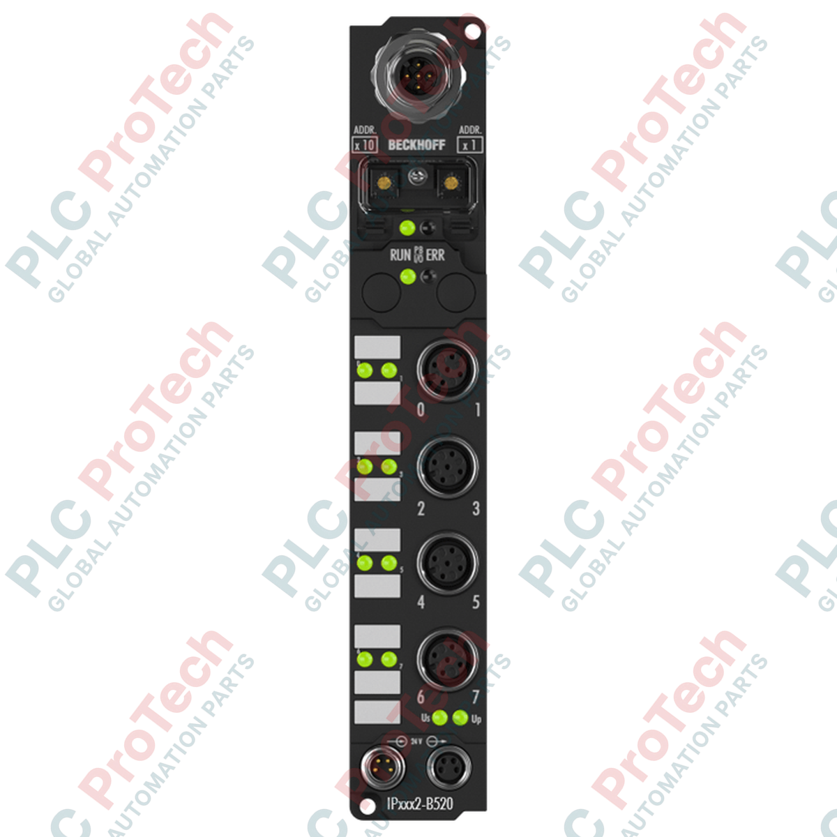
Product No.: IP2332-B520
Country of origin:Germany
Product Type: Fieldbus Boxes
Payment: T/T, Western Union
Weight: 500g
Dimensions: 2 x 2 x 0.25 mm
Shipping port: Xiamen
Warranty: 12 months
The BECKHOFF IP2332-B520 is a high-performance Fieldbus Box designed for decentralized I/O applications within DeviceNet industrial networks. Engineered to withstand demanding field conditions, this device enables direct machine-level signal routing without requiring a protective control cabinet. Its rugged enclosure and dust-tight, water-resistant design make it optimal for distributed installations across various automation architectures.
This module features integrated DeviceNet communication capabilities, enabling reliable data transmission over shielded copper cables. With support for automatic baud rate detection up to 500 kbaud, the BECKHOFF IP2332-B520 adapts to existing network configurations. The electrical isolation design provides high operational safety, separating the internal control electronics from the fieldbus communication lines to protect against noise and voltage surges.
| Manufacturer | BECKHOFF |
| Exact Model | IP2332-B520 |
| Product Type | Fieldbus Box |
| Protection Rating | IP65, IP66, IP67 (conforms to EN 60529) |
| Operating Temperature | 0 to +55 degC |
| Storage Temperature | -25 to +85 degC |
| Approvals and Markings | CE, UL |
| Protocol | DeviceNet |
| Bus Interface | 1 x M12 plug, 5-pin |
| Baud Rates | Automatic detection up to 500 kbaud |
| Data Transfer Medium | Shielded copper cable with power supply (typically 2 x 2 x 0.25 mm²) |
| I/O Communication Modes | Bit strobe, polling, cyclic, change of state |
| Maximum Station Distance | 500 m (at lower baud rates), 250 m, 100 m |
| Control Voltage | 24 V DC (-15% / +20%) |
| Box Supply Current | 45 mA + sensor current consumption (max. 0.5 A) |
| Power Connections | Feed: 1 x M8 male socket (4-pin); Downstream: 1 x M8 female socket (4-pin) |
| Electrical Isolation | 500 V (control voltage / fieldbus) |
| Vibration Resistance | Conforms to EN 60068-2-6 |
| Shock Resistance | Conforms to EN 60068-2-27 |
| Interface | Function |
|---|---|
| M12 Plug (5-pin) | DeviceNet network and communication interface connection |
| M8 Male Feed (4-pin) | 24 V DC control voltage input feed |
| M8 Female Downstream (4-pin) | 24 V DC control voltage connection to subsequent modules |
The BECKHOFF IP2332-B520 requires proper node configuration to communicate on the DeviceNet network. Users can establish parameters and define diagnostic interfaces using the BECKHOFF KS2000 software suite via the configuration interface, or directly through the master controller utilizing standard DeviceNet explicit messaging channels. Always verify that the baud rate and station addresses match your network plan during initial startup.

Global Express Shipping
Returns & Warranty
Global Express Shipping
Returns & Warranty
Orders are processed and delivered Monday-Friday (excluding public holidays).
For full eligibility, restocking fees, and international return details, please view our official Refund & Return Policy .
| Country of origin |
Germany
|

A field-first diagnostic sequence for 1756-OF4 analog output problems: channel mode, removable terminal block, scaling, and controlled electrical checks.

A direct comparison of 1746-OA8 and 1746-OA16 output count, common grouping, backplane current and temperature-derated load limits.

A field checklist for recording the 1761-NET-DNI hardware series, firmware, EDS file, DF1 settings, DeviceNet address and messaging configuration before replacement.

The EL3062 is a 0–10 V EtherCAT terminal. The EL3062-0030 is a 0–30 V variant. This checklist covers identification, scaling and commissioning.

A field checklist for replacing Allen-Bradley 1769-OW8 relay output modules without losing load-group, wiring, and commissioning details.

A field checklist for matching PLC digital and analog I/O to sensors, loads, commons, isolation groups, filters, and replacement settings.