1 of 3

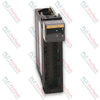
HIMA F 6705 Safety-Related 2-Fold Digital-to-Analog Converter Module

HIMA F 6705 Safety-Related 2-Fold Digital-to-Analog Converter Module

Only 10 item(s) left in stock
  • Manufacturer: HIMA

  • Product No.: F 6705

  • Country of origin:Germany

  • Product Type: Safety Analog Output Modules

  • Barcode: 8537101190

  • Payment: T/T, Western Union

  • Weight: 300g

  • Dimensions: 20 mm x 130 mm x 250 mm (W x H x D)

  • Shipping port: Xiamen

  • Warranty: 12 months

Quantity
View full details

Description

The HIMA F 6705 is a safety-related, 2-fold digital-to-analog converter module engineered for high-reliability process automation and safety-critical configurations. This device supports rigorous safety loop protocols across requirement classes AK 1 through AK 6. Featuring two individual galvanically isolated analog outputs with comprehensive safety isolation, the module integrates an embedded safety shutdown mechanism compatible with both source and sink operating modes. The F 6705 runs complete internal diagnostic self-test routines continuously during operation to secure functional integrity, verifying system parameters and preventing signal cross-talk.

Features

  • Automated Diagnostics: The module executes automatic, full self-test routines during active operation, monitoring the linearity of the DA converter, cross-talk between individual channels, safety shutdown paths, and signal resolution.
  • Safety Isolation: Individual galvanic isolation across output paths is integrated with hardware-level safety isolation and a dedicated safety shutdown function.
  • Dual Operating Modes: Flexible configuration capabilities enable independent output assignment for source mode or sink mode operation.
  • High-Resolution Conversion: An integrated 12-bit digital-to-analog converter provides 4,095 distinct operating steps.
  • Flexible Functional Wiring: The module accommodates standard front cable plug installations and supports specialized configurations, including redundant current connections and bipolar current operation.

Applications

  • Safety-instrumented loops demanding precise analog control across requirement classes AK 1 through AK 6.
  • Redundant current distribution loops using dual-channel configurations to maintain continuous signal output to the burden.
  • Bipolar current output applications ranging from -20 mA to +20 mA through synchronized multi-module pairings.

Technical Specifications

Parameter Value
Manufacturer HIMA Paul Hildebrandt GmbH + Co KG
Module Type 2-fold digital-to-analog converter, safety-related
Requirement Class AK 1 to AK 6
Outputs 0/4 to 20 mA
Resolution 12 bits (4,095 steps); 0 = 0 mA, 3,840 = 20 mA
Burden RB — Source Mode < 550 Ω, including line resistance to the burden
Burden RB — Sink Mode ≤ (UQ - 10 V) / 21.2 mA, where UQ is the source voltage
Basic Error ≤ 0.2% (40 µA) at 25°C
Operating Error ≤ 0.4% at 0 to +60°C
Line Length Maximum 1,000 m, subject to burden limits
Electric Strength 250 V against Analog GND
Basic Status with Plug-In I ≤ 40 µA in sink mode
Source Voltage UQ 10 to 30 V
Space Requirement 4 TE
Operating Data 5 V DC: 85 mA; 24 V DC: 130 mA

Connections and Interfaces

Lead Marking Cable Plug — Z 7126/6705/C..

Channel Connection Pin Color Cable Specification / Function
Channel 1 b8 WS LIYCY cable, 8 × 0.5 mm², length 750 mm
b6 br LIYCY cable, 8 × 0.5 mm², length 750 mm
b4 rs LIYCY cable, 8 × 0.5 mm², length 750 mm
b10 gr LIYCY cable, 8 × 0.5 mm², length 750 mm
Channel 2 b24 gn LIYCY cable, 8 × 0.5 mm², length 750 mm
b22 ge LIYCY cable, 8 × 0.5 mm², length 750 mm
b20 rt LIYCY cable, 8 × 0.5 mm², length 750 mm
b26 bl LIYCY cable, 8 × 0.5 mm², length 750 mm
L− b28 sw Flat pin plug, 2.8 × 0.8 mm; length 120 mm; conductor cross-section 1 mm²
L+ b32 rt Flat pin plug, 2.8 × 0.8 mm; length 120 mm; conductor cross-section 1 mm²
Cable Screen ge-gn Flat pin plug, 6.3 × 0.8 mm; connected to the earth bar; conductor cross-section 2.5 mm²

Installation Guidelines

  • Unused Channel Termination: To prevent module error messages, unused channels must be terminated with a hardware jumper across pins b6-b8 for channel 1 and pins b22-b24 for channel 2.
  • Shielding and Grounding: The yellow-green cable screen must be grounded through the 6.3 × 0.8 mm flat pin plug directly to the earth bar below the module slot.
  • Redundant Connection Rule: Parallel output channels must operate in the same mode. Both channels must use either source mode or sink mode. To improve load balancing and limit thermal errors, program each channel to supply half of the total target loop current, IG, to the burden resistance. In parallel redundant operation, the permissible total burden resistance is halved.
  • Bipolar Connection Constraints: For signed current output from -20 mA to +20 mA, only one module may actively generate or consume current at any time. This switching constraint must be implemented in the user application program.

Compliance and Certifications

  • TÜV
  • CE
Loading product navigation…

Product Documentation

Technical Datasheet (PDF) Complete specifications and technical drawings.

Technical Datasheet

HIMA F 6705 Safety-Related 2-Fold Digital-to-Analog Converter Module

What happens if an unused channel on the module is left completely open without termination?

Leaving an unused channel open will trigger module error messages. To avoid this issue, unused channels must be terminated with a jumper across pins b6-b8 for channel 1, or pins b22-b24 for channel 2.

How is the allowed burden resistance affected when pairing channels in a redundant current setup?

When connecting channels in parallel for a redundant current installation, the total maximum admissible burden resistance is reduced to half of its standard value.

Which specific hardware diagnostics does the device perform automatically during field operation?

The device automatically runs online verification routines checking the linearity of the DA-converter, signal cross-talk between active channels, safety shutdown pathways, and converter resolution.

What is the key programming rule for implementing a bipolar current connection?

To guarantee target system accuracy during bipolar operations, the user application logic must ensure that only one module actively generates or consumes current at any given time.

Global Express Shipping

  • Standard Delivery: 4-6 Business Days via DHL, FedEx, and UPS.
  • Express Dispatch: Same-day dispatch for in-stock orders placed before 2:00 PM (GMT+8).
  • Worldwide Coverage: Serving over 150 countries, including rapid delivery to Saudi Arabia and UAE.

Returns & Warranty

  • 30-Day Guarantee: Returns accepted for in-stock products in original, factory-sealed packaging.
  • 12-Month Warranty: Every industrial component is backed by our professional technical warranty.

Orders are processed and delivered Monday-Friday (excluding public holidays).


For full eligibility, restocking fees, and international return details, please view our official Refund & Return Policy .

TECHNICAL SPECIFICATIONS

Color pattern
Black
Country of origin
Germany
Power source
DC Power

Recently Viewed Products

Technical knowledge

Why Maintenance Data Is Essential for Industrial Reliability

Maintenance data connects work orders, sensor signals, asset history, costs, and technician knowledge. Used well, it improves planning, reliability, predictive maintenance, spare-parts control, and...

Electric Actuators Designed to Replace Fluid Power Systems: A Practical Industrial Automation Guide

This article explains how integrated electric actuators, such as SMC’s e-Actuator series, are transforming industrial motion control by replacing traditional pneumatic and hydraulic systems. It...

Math Operations Using OpenPLC for Industrial Automation Applications

This article explains how PLC systems perform core mathematical operations such as addition, subtraction, multiplication, division, modulo, and exponentiation within industrial automation. It shows...

Advanced Boolean Logic with FBD PLC Programming: Practical Industrial Applications Beyond Basic Logic

The article explains several advanced Boolean logic functions used in PLC programming beyond basic AND, OR, and NOT operations. It covers how tools like truth tables, multiplexers, pulse generators,...

Boolean Logic in PLC Programming: Understanding FBD Logic Gates

Boolean logic is the foundation of every PLC program. From simple machine controls to complex industrial automation systems, logic gates determine how controllers respond to changing inputs and...

Deep-Dive Guide to Industrial Firewalls and OT Network Segmentation

Industrial firewalls play a critical role in OT cybersecurity, protecting PLC, DCS, and SCADA networks through segmentation, ingress/egress control, and IDS/IPS integration aligned with IEC 62443...