


Commissioning PLX32-EIP-MBTCP: Subnets, Registers, and RPI
A commissioning checklist for the ProSoft PLX32-EIP-MBTCP covering subnet separation, register contracts, EtherNet/IP timing, failure tests and replacement records.
Manufacturer: HIMA
Product No.: F30 01
Country of origin:Germany
Product Type: Safety Controller Module
Barcode: 8537101190
Payment: T/T, Western Union
Weight: 1200g
Dimensions: 114 mm x 257 mm x 66 mm (H x W x D)
Shipping port: Xiamen
Warranty: 12 months
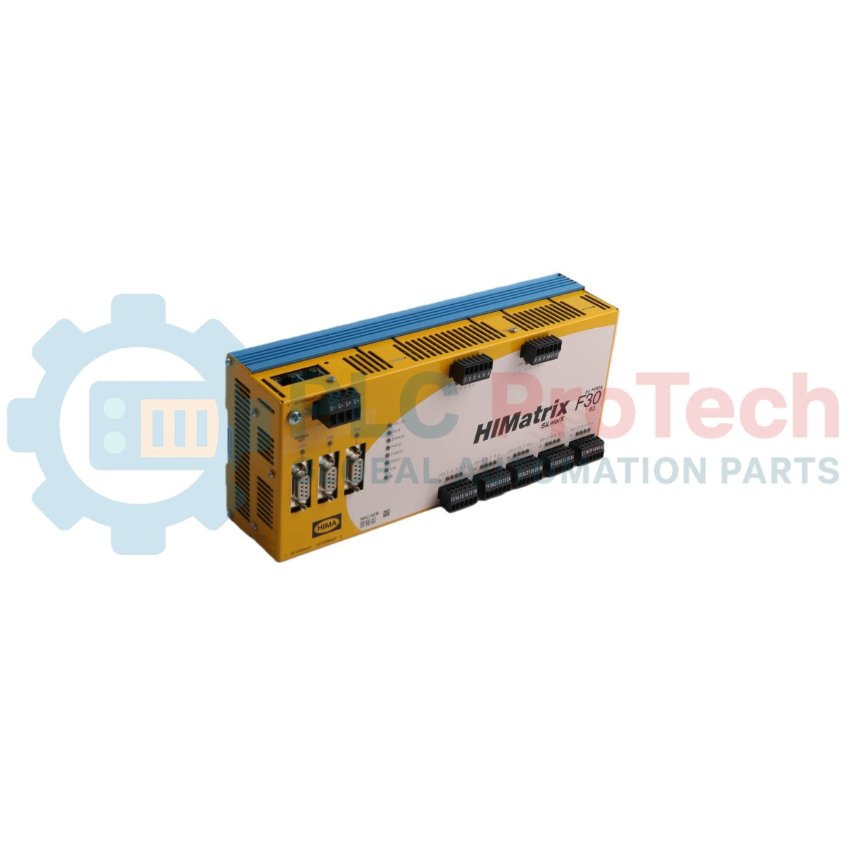
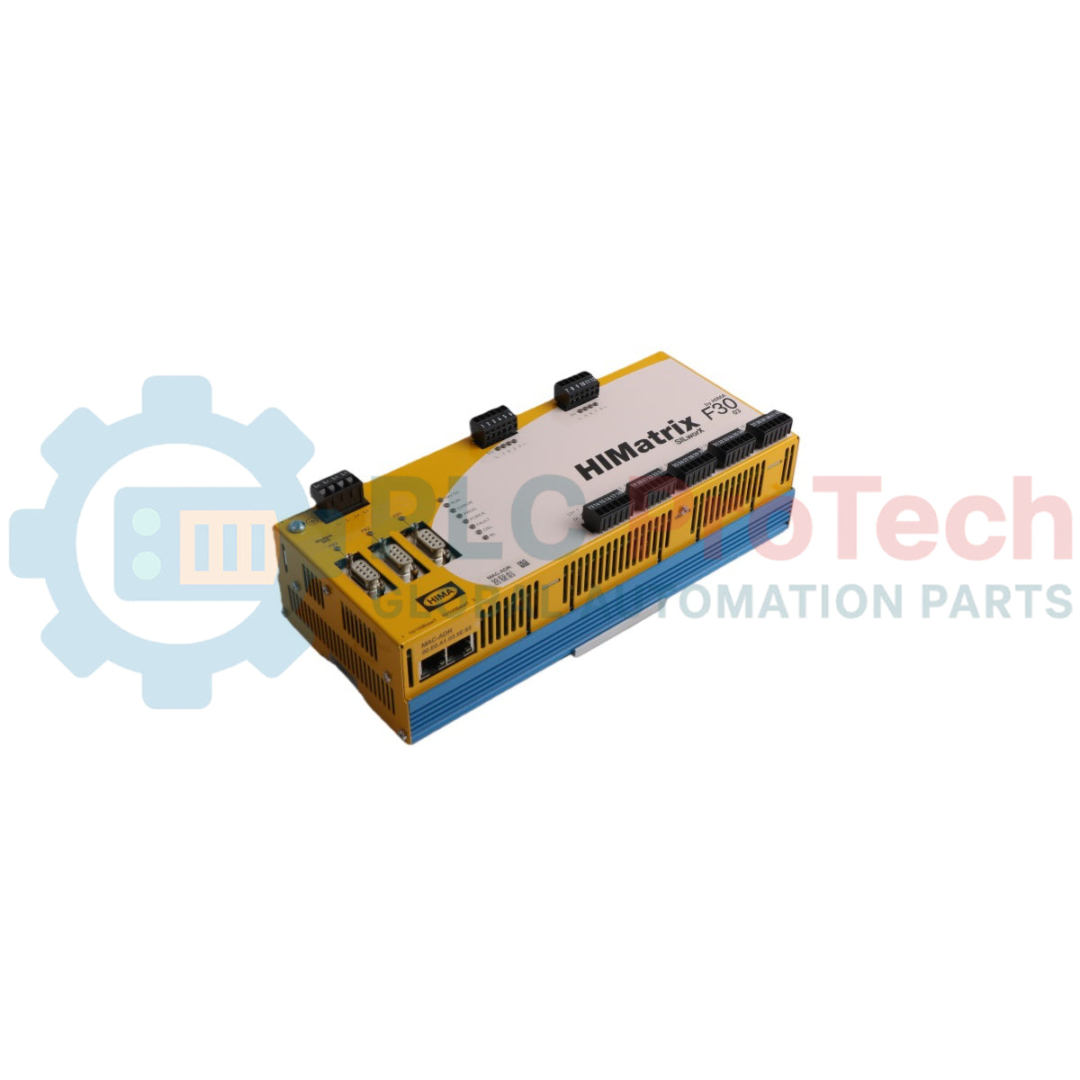
The HIMA F30 01 is a safety-related compact controller housed in a metal enclosure designed for safety-critical automation applications. Equipped with 20 safety-related digital inputs and 8 safety-related digital outputs, the F30 01 processes process logic under the de-energized-to-trip safety principle. The controller features four RJ-45 Ethernet ports with an integrated switch supporting safeethernet communication, as well as three 9-pole D-sub serial fieldbus interfaces for flexible industrial network integration. Engineered for high-reliability systems, the F30 01 is suitable for deployment in safety instrumented systems (SIS) and hazardous locations classified as Zone 2.
| Designation | Description | Part No. |
|---|---|---|
| F30 01 | Compact controller with 20 digital inputs and 8 digital outputs. Operating temperature 0 degC to +60 degC, for ELOP II Factory programming tool | 98 2200415 |
| F30 011 (-20 degC) | Compact controller with 20 digital inputs and 8 digital outputs. Operating temperature -20 degC to +60 degC, for ELOP II Factory programming tool | 98 2200455 |
| F30 01 SILworX | Compact controller with 20 digital inputs and 8 digital outputs. Operating temperature 0 degC to +60 degC, for SILworX programming tool | 98 2200472 |
| F30 011 SILworX (-20 degC) | Compact controller with 20 digital inputs and 8 digital outputs. Operating temperature -20 degC to +60 degC, for SILworX programming tool | 98 2200478 |
| Category | Parameter | Specification |
|---|---|---|
| General | Manufacturer | HIMA Paul Hildebrandt GmbH + Co KG |
| Country of Origin | Germany | |
| Dimensions | 114 mm x 257 mm x 66 mm (H x W x D with fixing bolt/screws) | |
| Weight | approx. 1.2 kg | |
| Electrical | Operating Voltage | 24 VDC (-15%...+20%, Wss <= 15%) from SELV/PELV power supply unit |
| Current Input | Max. 8 A (with maximum load); Idle: 0.5 A | |
| External Fuse | 10 A time-lag (T) | |
| Response Time | >= 20 ms | |
| Environmental | Operating Temperature | 0 degC to +60 degC (F30 01 standard); -20 degC to +60 degC (F30 011 model) |
| Storage Temperature | -40 degC to +85 degC | |
| Protection Class | Protection class III in accordance with IEC/EN 61131-2 | |
| Protection Type | IP20 | |
| Pollution Degree | Pollution degree II in accordance with IEC/EN 61131-2 | |
| Altitude | < 2000 m | |
| Digital Inputs | Quantity | 20 (non-galvanically isolated) |
| High Level | Voltage: 15...30 VDC; Current: >= 2 mA at 15 V | |
| Low Level | Voltage: max. 5 VDC; Current: max. 1.5 mA (1 mA at 5 V) | |
| Switching Point | typ. 7.5 V | |
| Sensor Supply | 5 x 20 V / 100 mA (at 24 V), short-circuit-proof | |
| Digital Outputs | Quantity | 8 (non-galvanically isolated) |
| Output Voltage | >= L+ minus 2 V | |
| Output Current | Channels 1...3 & 5...7: 0.5 A at 60 degC; Channels 4 & 8: 1 A at 60 degC, 2 A at 50 degC | |
| Minimum Load | 2 mA for each channel | |
| Internal Voltage Drop | max. 2 V at 2 A | |
| Leakage Current | max. 1 mA at 2 V (low level) | |
| Communication | Ethernet Ports | 4 x RJ-45, 10/100Base-T (with 100 Mbit/s) with integrated switch |
| Fieldbus Interfaces | FB1, FB2 (9-pole D-sub, optional submodules); FB3 (9-pole D-sub RS485) |
| Connector Pin | PROFIBUS DP Signal | RS485 Signal | RS232 Signal | RS422 Signal | INTERBUS Signal |
|---|---|---|---|---|---|
| 1 | - | - | - | - | DO |
| 2 | - | RP (+5 V) | TxD | RP (+5 V) | DI |
| 3 | RxD/TxD-A | RxD/TxD-A | RxD | RxA | COM |
| 4 | RTS | CNTR-A | - | TxA | - |
| 5 | DGND | DGND | DGND | DGND | - |
| 6 | VP (+5 V) | VP (+5 V) | - | VP (+5 V) | DO- |
| 7 | - | - | RTS | - | DI- |
| 8 | RxD/TxD-B | RxD/TxD-B | - | RxB | - |
| 9 | - | CNTR-B | - | TxB | - |
| Connector Pin | Function |
|---|---|
| 3 | RxD/TxD-A (Receive/send data A) |
| 4 | CNTR-A (Control signal A) |
| 5 | DGND (Data ground) |
| 6 | VP (+5 V supply voltage) |
| 8 | RxD/TxD-B (Receive/send data B) |
| 9 | CNTR-B (Control signal B) |
| Terminal | Designation | Function |
|---|---|---|
| 13, 19, 25, 31, 37 | LS+ | Sensor supply (for input groups 1..4, 5..8, 9..12, 13..16, 17..20) |
| 14, 15, 16, 17 | 1, 2, 3, 4 | Digital inputs 1 to 4 |
| 20, 21, 22, 23 | 5, 6, 7, 8 | Digital inputs 5 to 8 |
| 26, 27, 28, 29 | 9, 10, 11, 12 | Digital inputs 9 to 12 |
| 32, 33, 34, 35 | 13, 14, 15, 16 | Digital inputs 13 to 16 |
| 38, 39, 40, 41 | 17, 18, 19, 20 | Digital inputs 17 to 20 |
| 18, 24, 30, 36, 42 | L- | Ground |
| Terminal | Designation | Function |
|---|---|---|
| 1, 7 | LS+ | Sensor supply / power supply connection |
| 2, 3, 4, 5 | 1, 2, 3, 4 | Digital outputs 1, 2, 3 (0.5 A) and 4 (1 A / 2 A) |
| 8, 9, 10, 11 | 5, 6, 7, 8 | Digital outputs 5, 6, 7 (0.5 A) and 8 (1 A / 2 A) |
| 6, 12 | L- | Ground channel group |


Global Express Shipping
Returns & Warranty
Global Express Shipping
Returns & Warranty
Orders are processed and delivered Monday-Friday (excluding public holidays).
For full eligibility, restocking fees, and international return details, please view our official Refund & Return Policy .
| Color pattern |
Dots
|
| Country of origin |
Germany
|
| Power source |
DC Power
|

A commissioning checklist for the ProSoft PLX32-EIP-MBTCP covering subnet separation, register contracts, EtherNet/IP timing, failure tests and replacement records.

A field checklist for IC693MDL916 relay commands, terminal blocks, load current, switching rate and contact-side measurements.

A field checklist for KL1512 signal thresholds, counter direction, process data and the KL1512-to-KS1512 wiring difference.

A field checklist for EPP2008-0001 current limits, supply voltage, channel LEDs, connector coding and load-related output faults.

Before moving a TwinCAT 3 license with a Beckhoff C9900-L100, verify the TwinCAT build, XML device description, exact order code and cabinet limits.

A field checklist for replacing a Beckhoff EL4032, covering the ±10 V load, terminal map, power contacts, EtherCAT state, and watchdog behavior.