ICS Triplex

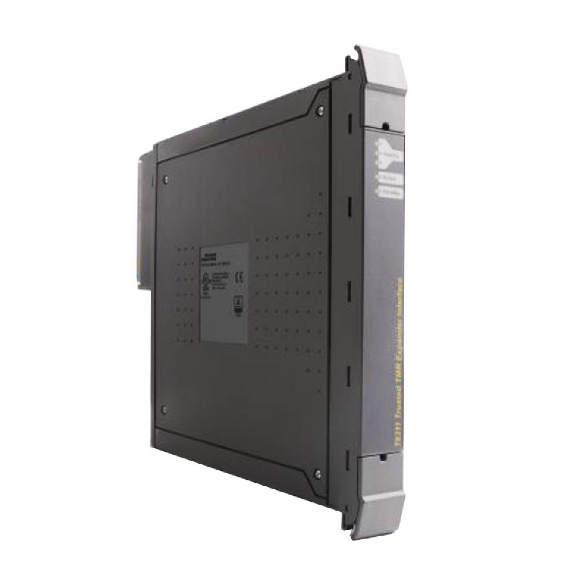
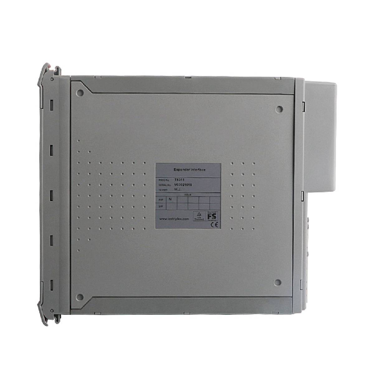
ICS Triplex T8311 Trusted TMR Expander Interface

SKU T8311

In stock
  • 12-month warranty
  • Free returns within 30 days
  • Manufacturer: ICS Triplex

  • Product No.: T8311

  • Country of origin:United States

  • Product Type: Trusted TMR Expander Interface

  • Barcode: 8537101190

  • Payment: T/T, Western Union

  • Weight: 1140g

  • Dimensions: 266 mm x 31 mm x 303 mm (H x W x D)

  • Shipping port: Xiamen

  • Warranty: 12 months

Description

The ICS Triplex T8311 is a Triple Modular Redundant (TMR) expander interface module designed for the Trusted safety and critical control system chassis. Operating within an I/O module slot of the main Controller Chassis, this module serves as the master interface bridging the internal Inter-Module Bus (IMB) and the external Expander Bus. The T8311 executes hardware-implemented fault tolerant (HIFT) operations to extend high-bandwidth, fault-tolerant chassis communication across multiple expander chassis using unshielded twisted pair (UTP) cabling or fiber-optic connections. By providing full fault containment across three main Fault Containment Regions (FCR A, B, and C), the expander interface module isolates potential faults to maximize system availability in safety instrumented functions (SIF) and critical process control applications.

Features

  • Triple Modular Redundant (TMR) fault tolerant architecture supporting 3-2-0 operation.
  • Hardware Implemented Fault Tolerant (HIFT) design with Byzantine voting across Fault Containment Regions.
  • Fast fault recognition and automatic fault handling without nuisance alarming.
  • Support for hot replacement and hot-standby pair configurations.
  • Front panel LED indicators displaying overall module health, active state, and standby state.

Applications

  • Safety Instrumented Systems (SIS)
  • Emergency Shutdown (ESD) systems
  • Critical process control and burner management systems
  • Distributed multi-chassis safety automation systems requiring remote expansion

Technical Specifications

Parameter Specification
Manufacturer Rockwell Automation / ICS Triplex
Module Type TMR Expander Interface Module
Module Location T8100 I/O Module Slot
Backplane (IMB) Supply Voltage 20 Vdc to 32 Vdc
Power Dissipation 54 W Backplane Supply
Field Supply N/A
Isolation 50 V Basic Insulation, Module to Backplane Supply
Fusing Not User Serviceable
Expander Bus Data Rate 1.5 Gbps
Inter-Module Bus Data Rate Up to 12.5 Mbps
Max Distance (UTP Copper Cable TC-301) 30 m
Max Distance (T8314 Fiber TX/RX) 10 km
Operating Temperature 0 degC to +60 degC (+32 degF to +140 degF)
Storage Temperature -25 degC to +70 degC (-13 degF to +158 degF)
Relative Humidity 10%-95%, non-condensing
Dimensions (H x W x D) 266 mm x 31 mm x 303 mm (10.5 in x 1.2 in x 12.0 in)
Weight 1.14 kg (2.5 lb)

Connections/Interfaces

Connector Pin Function
SK1 185-way DIN41642 Backplane IMB Connector
PL4 96-way DIN41612 C-type Expander Chassis Bus Connector

Installation Guidelines

  • Slot Configuration: Install modules in adjacent I/O slots within the Controller Chassis as a pair, starting with an odd-numbered slot on the left.
  • Interconnection: Use the T8312 Expander Interface Adapter Unit to interconnect paired interface slots.
  • Mechanical Keying: Ensure field cable keying pins 1, 2, and 6 are removed for the T8311 module prior to fitting.
  • Handling Precautions: Static sensitive components are present; observe ESD handling precautions and do not touch exposed connector pins or open the module housing.
  • Hot Swapping: When replacing an active module, release top and bottom ejectors and wait until the module transitions to standby mode before removal. Never remove an active module.

Compliance and Certifications

  • TÜV Certified IEC 61508 SIL 3

FAQ

What is the primary function of the expander interface module?

The module acts as the master interface bridging the Inter-Module Bus in the controller chassis with the Expander Bus, enabling multi-chassis expansion while maintaining fault-tolerant communication.

What is the maximum communication distance supported by the device?

The device supports up to 30 m using UTP copper cables (TC-301) and up to 10 km when using fiber optic transceivers (T8314).

How should the module be safely removed during online operation?

Release both ejector tabs and wait until the active indicator turns off and the standby indicator illuminates before removing the module to prevent system shutdown.

View all FAQs →

Product Documentation

Technical Datasheet (PDF) Complete specifications and technical drawings.

Technical Datasheet

ICS Triplex T8311 Trusted TMR Expander Interface

Quantity
Shipping & Returns

Global Express Shipping

  • Standard Delivery: 4–6 business days via DHL, FedEx, and UPS.
  • Express Dispatch: Same-day dispatch for in-stock orders placed before 2:00 PM (GMT+8).
  • Worldwide Coverage: Serving over 150 countries.

Returns & Warranty

  • 30-Day Guarantee: Returns accepted for in-stock products in original, factory-sealed packaging.
  • 12-Month Warranty: Every industrial component is backed by our technical warranty.
Reviews
1 of 2
Only 20 item(s) left in stock
Quantity
View full details

Global Express Shipping

  • Standard Delivery: 4-6 Business Days via DHL, FedEx, and UPS.
  • Express Dispatch: Same-day dispatch for in-stock orders placed before 2:00 PM (GMT+8).
  • Worldwide Coverage: Serving over 150 countries, including rapid delivery to Saudi Arabia and UAE.

Returns & Warranty

  • 30-Day Guarantee: Returns accepted for in-stock products in original, factory-sealed packaging.
  • 12-Month Warranty: Every industrial component is backed by our professional technical warranty.

Orders are processed and delivered Monday-Friday (excluding public holidays).


For full eligibility, restocking fees, and international return details, please view our official Refund & Return Policy .

TECHNICAL SPECIFICATIONS

Country of origin
United States

Technical knowledge

Light-On and Dark-On Photoelectric Sensor Logic

Learn how light-on and dark-on photoelectric sensor modes interact with through-beam, retroreflective, and diffuse sensing, PNP/NPN wiring, PLC logic, commissioning, and fault detection.

Designing H-Bridge Motor Drives Without Shoot-Through

A practical guide to H-bridge motor drives covering switching states, dead time, inductive current paths, PWM choices, protection, PCB layout, PLC interfacing, and staged commissioning tests.

Designing Mitsubishi FX PLC Sequences with STL and RET

Learn how Mitsubishi FX PLC STL and RET instructions structure conveyor and pneumatic sequences, with practical state design, transition logic, timeouts, diagnostics, and safe restart boundaries.

Selecting and Troubleshooting DIN Valve Connectors

A practical guide to selecting, wiring and diagnosing DIN-style valve connectors, including form identification, coil voltage, suppression, polarity, sealing, release-time effects and commissioning...

PLC or Microcontroller for Arc-Welding Motion Control?

A PLC and a microcontroller can both generate step-and-direction motion, but arc welding exposes major differences in EMC, I/O protection, diagnostics, maintainability, safety integration, and...

Piezo Pneumatic Valves: Precision, Power, and Design Limits

Piezo pneumatic valves offer low holding power and fine proportional control, but they are not universal solenoid replacements. This guide covers driver electronics, flow limits, contamination, fail...