ICS Triplex

ICS Triplex T9100 AADvance Processor Base Unit

SKU T9100

In stock
  • 12-month warranty
  • Free returns within 30 days
  • Manufacturer: ICS Triplex
  • Product No.: T9100
  • Origin United States
  • Product Type: AADvance Processor Backplane
  • Barcode: 8537101190
  • Payment: T/T, Western Union
  • Weight: 0.46 kg
  • Dimensions: 126 mm x 235 mm x 118 mm (W x H x D)
  • Shipping port: Xiamen
  • Warranty: 12 months

Tags

Product Documentation

Technical Datasheet (PDF) Complete specifications and technical drawings.

Technical Datasheet

ICS Triplex T9100 AADvance Processor Base Unit

Quantity

Product Description

Description

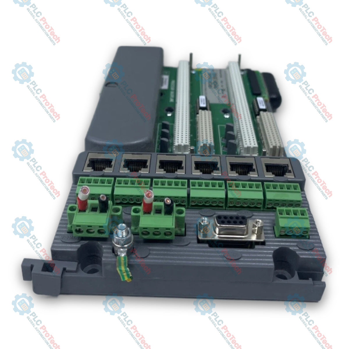
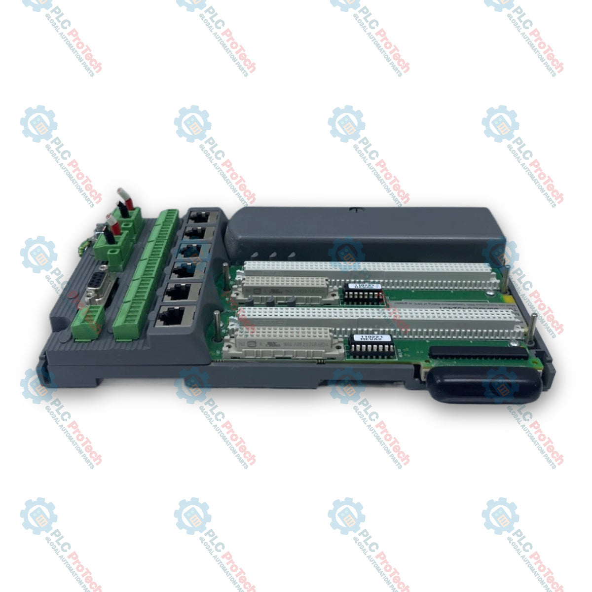
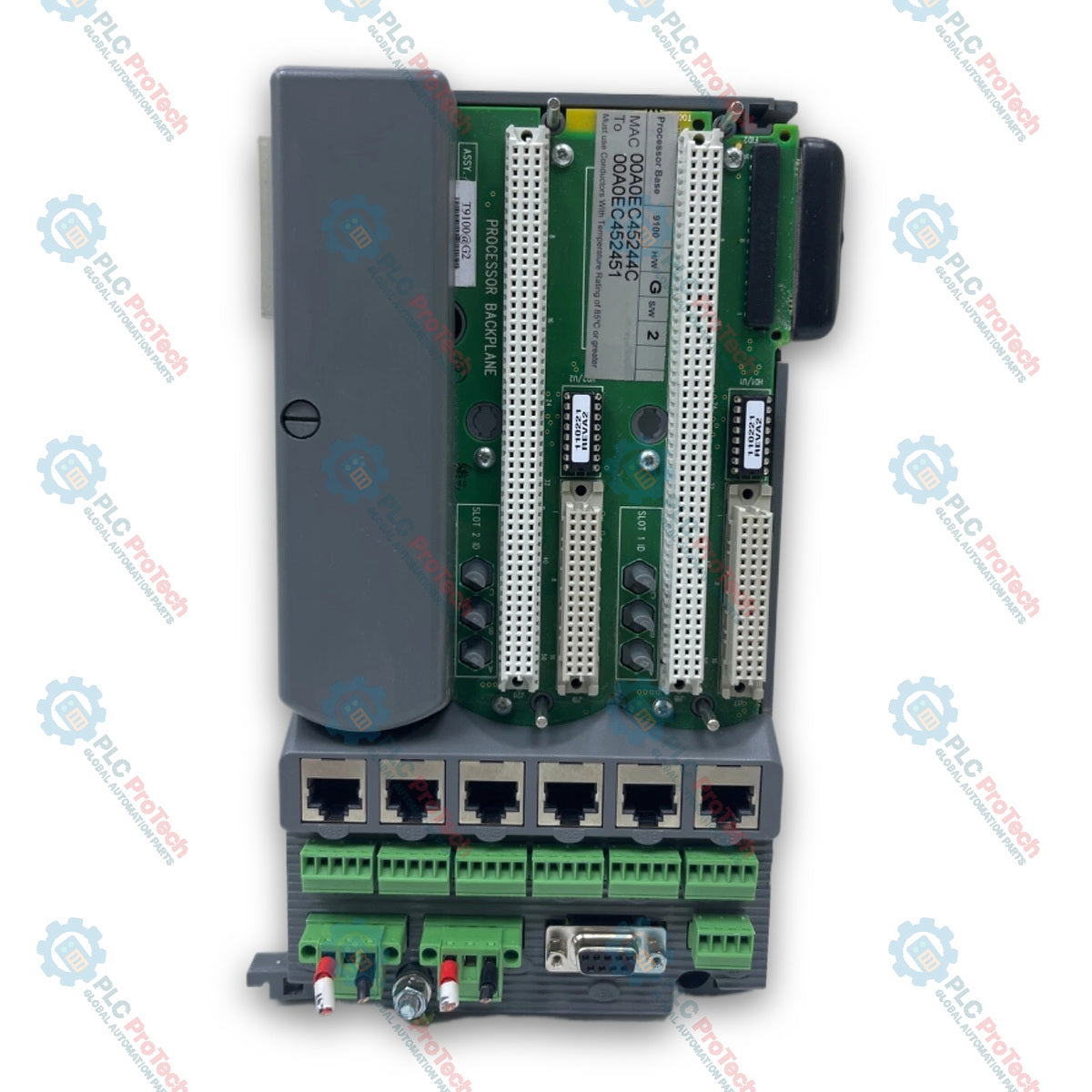
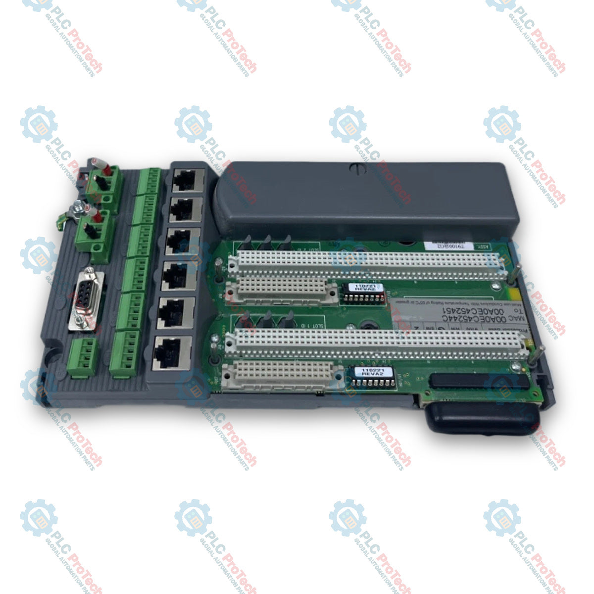
The ICS Triplex T9100 is a processor base unit designed for the primary electrical interconnectivity and housing of processor modules within safety instrumented systems and critical control applications. The unit supplies internal system power and electrical connections between up to three T9110 processor modules in a redundant group, as well as providing communication routing to downstream I/O base units over dual command and response buses. Communication hardware on the unit features six shielded RJ45 Ethernet sockets (E1-1 through E3-2) adhering to IEC 60603-7, six 5-way serial port connectors (S1-1 through S3-2), dual 3-way power supply connectors (PWR-1, PWR-2), and a dedicated Program Enable Key interface. Hardware identification is preserved independently per slot via an internal factory-installed BUSP component, allowing individual processor modules to be swapped without reconfiguring network IP addresses.

Features

  • Integrated backplane supporting 1, 2, or 3 processor modules operating as a redundant group
  • Dedicated physical support for up to 16 I/O base units across dual independent I/O buses
  • Onboard BUSP hardware component retaining individual processor IP addresses for seamless module replacement
  • Dual redundant +24 Vdc power input terminal connections
  • Direct panel mounting holes and integrated slots/clamps for standard DIN rail mounting
  • Six shielded RJ45 Ethernet ports for dedicated network connections across installed processors
  • Dedicated Program Enable Key connector interface

Applications

  • Emergency Shutdown Systems (ESD)
  • Fire and Gas Detection Systems (F&G)
  • Burner Management Systems (BMS)
  • Critical process control and Safety Instrumented Systems (SIS) up to SIL 3

Technical Specifications

Parameter Specification
Manufacturer ICS Triplex / Rockwell Automation
Supply Voltage Requirements Redundant +24 Vdc nominal (18 Vdc to 32 Vdc range)
Number of Processor Modules Supported 1, 2, or 3
Number of I/O Base Units Supported 16 (8 for each I/O bus)
Dimensions (Height x Width) 235 mm x 126 mm (9 1/4 in. x 5 in.)
Weight 460 g (16 oz.)

Connections/Interfaces

Connector Pin Function
E1-1, E1-2 Connectors for Ethernet Ports 1 & 2 for Processor A (Shielded RJ45, IEC 60603-7)
E2-1, E2-2 Connectors for Ethernet Ports 1 & 2 for Processor B (Shielded RJ45, IEC 60603-7)
E3-1, E3-2 Connectors for Ethernet Ports 1 & 2 for Processor C (Shielded RJ45, IEC 60603-7)
S1-1, S1-2 Connectors for Serial Ports 1 & 2 for Processor A (5-way connector, max 1.31 mm² / 16 AWG)
S2-1, S2-2 Connectors for Serial Ports 1 & 2 for Processor B (5-way connector, max 1.31 mm² / 16 AWG)
S3-1, S3-2 Connectors for Serial Ports 1 & 2 for Processor C (5-way connector, max 1.31 mm² / 16 AWG)
PWR-1, PWR-2 Connectors for Redundant +24 Vdc Power Supplies (3-way connector, max 3.3 mm² / 12 AWG)
FLT Not used
KEY Connector for the Program Enable Key

Installation Guidelines

  • Secure the base unit to a flat panel surface using the integrated screw mounting holes or snap firmly onto standard DIN rails via the integrated clamps.
  • Wire redundant +24 Vdc supply connections to PWR-1 and PWR-2 terminals using conductors up to 3.3 mm² (12 AWG) with a 7 mm (9/32 in.) strip length.
  • Attach serial port wiring to the 5-way terminal blocks S1-1 through S3-2 using conductors up to 1.31 mm² (16 AWG) with a 7 mm strip length.
  • Connect network cables using 2-pair or 4-pair shielded RJ45 connectors into ports E1-1 through E3-2.
  • Ensure adequate surrounding clearance within the enclosure to facilitate heat dissipation and cable routing.
Shipping & Returns

Global Express Shipping

  • Standard Delivery: 4–6 business days via DHL, FedEx, and UPS.
  • Express Dispatch: Same-day dispatch for in-stock orders placed before 2:00 PM (GMT+8).
  • Worldwide Coverage: Serving over 150 countries.

Returns & Warranty

  • 30-Day Guarantee: Returns accepted for in-stock products in original, factory-sealed packaging.
  • 12-Month Warranty: Every industrial component is backed by our technical warranty.
FAQ
How many I/O base units can connect to the base unit?
The base unit supports up to 16 total I/O base units split evenly with 8 on each I/O bus.
What power supply range does the base unit accept?
The unit operates on a redundant nominal +24 Vdc input voltage within an allowable range of 18 to 32 Vdc.
How are replacement processor network addresses preserved during module swaps?
An onboard factory-installed BUSP component retains the specific IP address for each processor slot independently.
Reviews

T9100

Stock & lead time on request

Call
1 of 4

ICS Triplex T9100 AADvance Processor Base Unit

Only 19 item(s) left in stock
  • Manufacturer: ICS Triplex

  • Product No.: T9100

  • Country of origin:United States

  • Product Type: AADvance Processor Backplane

  • Barcode: 8537101190

  • Payment: T/T, Western Union

  • Weight: 460g

  • Dimensions: 126 mm x 235 mm x 118 mm (W x H x D)

  • Shipping port: Xiamen

  • Warranty: 12 months

Quantity
View full details

Description

The ICS Triplex T9100 is a processor base unit designed for the primary electrical interconnectivity and housing of processor modules within safety instrumented systems and critical control applications. The unit supplies internal system power and electrical connections between up to three T9110 processor modules in a redundant group, as well as providing communication routing to downstream I/O base units over dual command and response buses. Communication hardware on the unit features six shielded RJ45 Ethernet sockets (E1-1 through E3-2) adhering to IEC 60603-7, six 5-way serial port connectors (S1-1 through S3-2), dual 3-way power supply connectors (PWR-1, PWR-2), and a dedicated Program Enable Key interface. Hardware identification is preserved independently per slot via an internal factory-installed BUSP component, allowing individual processor modules to be swapped without reconfiguring network IP addresses.

Features

  • Integrated backplane supporting 1, 2, or 3 processor modules operating as a redundant group
  • Dedicated physical support for up to 16 I/O base units across dual independent I/O buses
  • Onboard BUSP hardware component retaining individual processor IP addresses for seamless module replacement
  • Dual redundant +24 Vdc power input terminal connections
  • Direct panel mounting holes and integrated slots/clamps for standard DIN rail mounting
  • Six shielded RJ45 Ethernet ports for dedicated network connections across installed processors
  • Dedicated Program Enable Key connector interface

Applications

  • Emergency Shutdown Systems (ESD)
  • Fire and Gas Detection Systems (F&G)
  • Burner Management Systems (BMS)
  • Critical process control and Safety Instrumented Systems (SIS) up to SIL 3

Technical Specifications

Parameter Specification
Manufacturer ICS Triplex / Rockwell Automation
Supply Voltage Requirements Redundant +24 Vdc nominal (18 Vdc to 32 Vdc range)
Number of Processor Modules Supported 1, 2, or 3
Number of I/O Base Units Supported 16 (8 for each I/O bus)
Dimensions (Height x Width) 235 mm x 126 mm (9 1/4 in. x 5 in.)
Weight 460 g (16 oz.)

Connections/Interfaces

Connector Pin Function
E1-1, E1-2 Connectors for Ethernet Ports 1 & 2 for Processor A (Shielded RJ45, IEC 60603-7)
E2-1, E2-2 Connectors for Ethernet Ports 1 & 2 for Processor B (Shielded RJ45, IEC 60603-7)
E3-1, E3-2 Connectors for Ethernet Ports 1 & 2 for Processor C (Shielded RJ45, IEC 60603-7)
S1-1, S1-2 Connectors for Serial Ports 1 & 2 for Processor A (5-way connector, max 1.31 mm² / 16 AWG)
S2-1, S2-2 Connectors for Serial Ports 1 & 2 for Processor B (5-way connector, max 1.31 mm² / 16 AWG)
S3-1, S3-2 Connectors for Serial Ports 1 & 2 for Processor C (5-way connector, max 1.31 mm² / 16 AWG)
PWR-1, PWR-2 Connectors for Redundant +24 Vdc Power Supplies (3-way connector, max 3.3 mm² / 12 AWG)
FLT Not used
KEY Connector for the Program Enable Key

Installation Guidelines

  • Secure the base unit to a flat panel surface using the integrated screw mounting holes or snap firmly onto standard DIN rails via the integrated clamps.
  • Wire redundant +24 Vdc supply connections to PWR-1 and PWR-2 terminals using conductors up to 3.3 mm² (12 AWG) with a 7 mm (9/32 in.) strip length.
  • Attach serial port wiring to the 5-way terminal blocks S1-1 through S3-2 using conductors up to 1.31 mm² (16 AWG) with a 7 mm strip length.
  • Connect network cables using 2-pair or 4-pair shielded RJ45 connectors into ports E1-1 through E3-2.
  • Ensure adequate surrounding clearance within the enclosure to facilitate heat dissipation and cable routing.

Product Documentation

Technical Datasheet (PDF) Complete specifications and technical drawings.

Technical Datasheet

ICS Triplex T9100 AADvance Processor Base Unit

How many I/O base units can connect to the base unit?

The base unit supports up to 16 total I/O base units split evenly with 8 on each I/O bus.

What power supply range does the base unit accept?

The unit operates on a redundant nominal +24 Vdc input voltage within an allowable range of 18 to 32 Vdc.

How are replacement processor network addresses preserved during module swaps?

An onboard factory-installed BUSP component retains the specific IP address for each processor slot independently.

Global Express Shipping

  • Standard Delivery: 4-6 Business Days via DHL, FedEx, and UPS.
  • Express Dispatch: Same-day dispatch for in-stock orders placed before 2:00 PM (GMT+8).
  • Worldwide Coverage: Serving over 150 countries, including rapid delivery to Saudi Arabia and UAE.

Returns & Warranty

  • 30-Day Guarantee: Returns accepted for in-stock products in original, factory-sealed packaging.
  • 12-Month Warranty: Every industrial component is backed by our professional technical warranty.

Orders are processed and delivered Monday-Friday (excluding public holidays).


For full eligibility, restocking fees, and international return details, please view our official Refund & Return Policy .

TECHNICAL SPECIFICATIONS

Country of origin
United States

Recently Viewed Products

Technical knowledge

Implementing 3-Switch XOR Ladder Logic with Internal Bit

Implement a 3-SPST switch XOR light circuit in LogixPro or RSLogix 500 using an internal relay bit. Includes truth tables, boolean equations, and verified.

Building a Modbus RTU Network with CompactLogix and DeltaV

Integrate Allen-Bradley CompactLogix, Caterpillar ATS, and generators into DeltaV DCS over Modbus RTU. Covers ProSoft MVI69-MCM, Miille DIN266 gateways.

ONS Instruction Not Energizing OTE in Studio 5000 Ladder Logic

ONS instruction fires but the OTE coil never latches in Studio 5000 because the one-shot is only true for one scan. Use OTL/OTU or seal-in logic instead.

Kinetix 5500 EtherNet/IP Network Switch Requirements and Topology

Configure Allen-Bradley Kinetix 5500 servo drives on EtherNet/IP. Covers CIP Sync, IEEE 1588 V2 timing, Stratix selection, DLR topology, and HMI.

Moving Average Filtering in DCS and PLC Analog Control

A moving-average filter is the sliding-window smoother most instrument engineers drop into DCS and PLC analog paths. Here is how the window works, how N and sample time set lag, and when a...

GE Mark VI Function Blocks for Gas Turbine Control Logic

On Frame 5–9 gas turbines, GE Mark VI and Mark VIe run control as function-block application software. This article maps process, protection, and sequencing functions—and what Toolbox ST access...