ICS Triplex

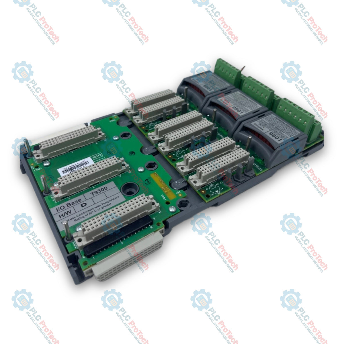
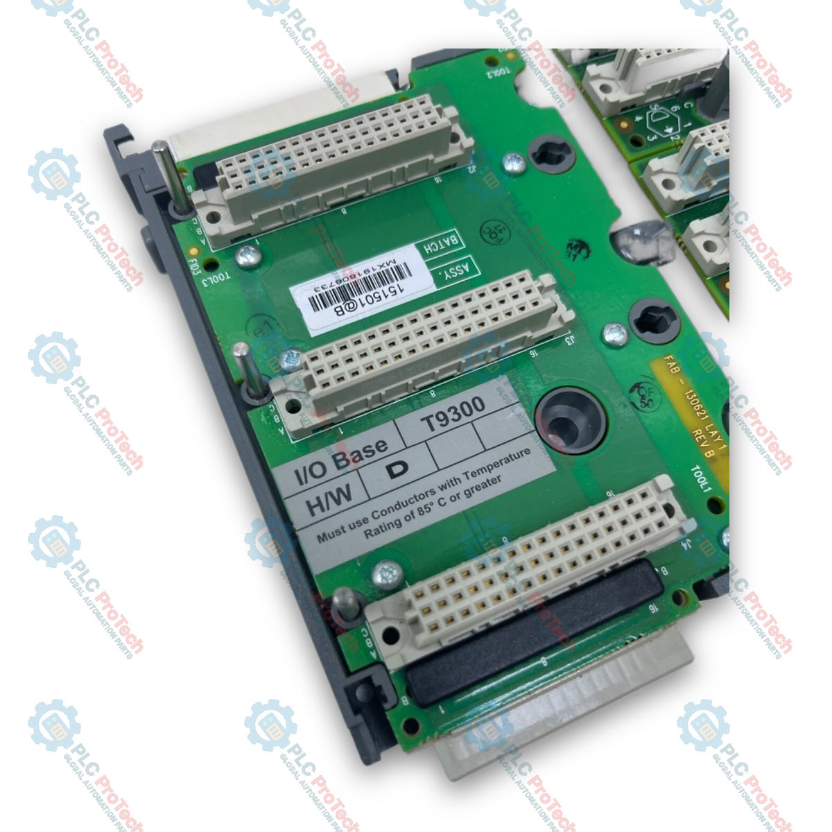
ICS Triplex T9300 AADvance I/O Base Unit

SKU T9300

In stock
  • 12-month warranty
  • Free returns within 30 days
  • Manufacturer: ICS Triplex
  • Product No.: T9300
  • Origin United States
  • Product Type: I/O Base Unit
  • Barcode: 8537101190
  • Payment: T/T, Western Union
  • Weight: 0.35 kg
  • Dimensions: 126 mm x 233 mm x 18 mm (W x H x D)
  • Shipping port: Xiamen
  • Warranty: 12 months

Tags

Product Documentation

Technical Datasheet (PDF) Complete specifications and technical drawings.

Technical Datasheet

ICS Triplex T9300 AADvance I/O Base Unit

Quantity

Product Description

Description

The ICS Triplex T9300 is an I/O base unit designed for functional safety and critical control applications within the AADvance system architecture. It serves as the physical and electrical backplane interface that holds up to three AADvance I/O modules, connecting them to command and response buses and mating directly with termination assemblies to route field wiring. Grounded in a high-density compact design, the T9300 features integrated side connectors and locking plastic clips that allow direct plug-and-socket bus expansion across multiple I/O base unit rows without requiring inter-module wiring.

Features

  • Accommodates up to three AADvance I/O modules per base unit
  • Mates directly with simplex, dual, and triple (TMR) field termination assemblies
  • Interconnects side-by-side using integrated bus connectors and plastic locking clips
  • Supports multi-row extension via T9310 expansion cables
  • Provides vertical DIN rail (TS35) or direct panel mounting options
  • Conformally coated printed circuit boards meeting MIL-1-46058C and IPC-CC-830 standards

Applications

  • Emergency Shutdown (ESD) Systems
  • Fire and Gas (F&G) Protection Systems
  • Critical Process Control Applications
  • Burner Management Systems (BMS)
  • Boiler and Furnace Control

Ordering Information

Catalog Number Description
T9300 AADvance I/O Base Unit

Technical Specifications

Parameter Specification
Manufacturer Rockwell Automation / Allen-Bradley
Model T9300
Product Type I/O Base Unit
Module Capacity Up to 3 I/O modules per base unit
Backplane Voltage Range 18 Vdc to 32 Vdc
Maximum Backplane Current 9.6 A (400 mA per slot)
Operating Temperature -25 degC to +60 degC (-13 degF to +140 degF)
Storage Temperature -40 degC to +70 degC (-40 degF to +158 degF)
Operating Humidity 10% to 95% RH, non-condensing
Operating Altitude 0 m to 2,000 m (0 ft to 6,600 ft)
Vibration (Withstand) 10 Hz to 150 Hz, 0.1 g acceleration in 3 axes
Shock (Operating) 15 g peak, 11 ms duration, half sine
Dimensions (H x W x D) 233 mm x 126 mm x 18 mm (approx.)
Environmental Protection IP20 (Base Unit Assembly)
Pollution Degree Rating Pollution Degree 2 (per IEC 60664-1)

Installation Guidelines

  • Mounting Orientation: Must be installed in the vertical orientation only when used in certified safety or hazardous environment applications.
  • Mounting Options: Secure to a pair of parallel TS35 standard symmetric DIN rails (35 mm x 7.5 mm) or direct panel mount using three M5 screws per base unit.
  • Clearance Requirements: Maintain a minimum clearance of 50 mm above and below the base unit for field wiring adjustment and module latching/removal, 30 mm to the right, and at least 140 mm front depth clearance from the mounting panel.
  • Enclosure Requirements: Must be installed inside an IP54 tool-accessible enclosure suitable for Pollution Degree 2 environments for both non-hazardous and ATEX/IECEx Class I, Division 2 hazardous locations.
  • Base Unit Interconnection: Connect adjacent I/O base units to the right side of the T9100 processor base unit or another T9300 base unit using direct plug-and-socket headers, securing the top and bottom with plastic locking clips.
  • Expansion Cables: Use T9310 expansion cables to route I/O Bus connections to additional base unit rows; ensure total bus length does not exceed 8 meters.

Compliance and Certifications

  • UL Listed: File E341697 (UL508, CSA C22.2 No 142)
  • Hazardous Location Certification: Class I, Division 2, Groups A, B, C, D (ANSI/ISA 12.12.01-2013, CSA C22.2 No 213-M1987, File E251761)
  • ATEX: DEMKO 11 ATEX 1129711X, Ex nA IIC T4 Gc (EN 60079-0, EN 60079-15)
  • IECEx: IECEx UL 12.0032X
  • Functional Safety: Certified for SIL 2 and SIL 3 applications in accordance with IEC 61508
  • EMC: KCC-EMC Registration Class A
Shipping & Returns

Global Express Shipping

  • Standard Delivery: 4–6 business days via DHL, FedEx, and UPS.
  • Express Dispatch: Same-day dispatch for in-stock orders placed before 2:00 PM (GMT+8).
  • Worldwide Coverage: Serving over 150 countries.

Returns & Warranty

  • 30-Day Guarantee: Returns accepted for in-stock products in original, factory-sealed packaging.
  • 12-Month Warranty: Every industrial component is backed by our technical warranty.
FAQ
How many module slots does the base unit provide for I/O expansion?
The base unit accommodates up to three plug-in AADvance I/O modules per unit.
Which mounting orientation is required for hazardous area compliance?
The base unit must be installed strictly in the vertical orientation inside an IP54 rated enclosure.
What is the maximum allowed bus length when extending base unit rows?
The total combined length of I/O base units and T9310 expansion cables cannot exceed 8 meters.
How are adjacent base units physically secured together on a DIN rail?
Adjacent base units connect via side pin headers and are locked using top and bottom plastic clips.
Reviews

T9300

Stock & lead time on request

Call
1 of 2

ICS Triplex T9300 AADvance I/O Base Unit

Only 19 item(s) left in stock
  • Manufacturer: ICS Triplex

  • Product No.: T9300

  • Country of origin:United States

  • Product Type: I/O Base Unit

  • Barcode: 8537101190

  • Payment: T/T, Western Union

  • Weight: 350g

  • Dimensions: 126 mm x 233 mm x 18 mm (W x H x D)

  • Shipping port: Xiamen

  • Warranty: 12 months

Quantity
View full details

Description

The ICS Triplex T9300 is an I/O base unit designed for functional safety and critical control applications within the AADvance system architecture. It serves as the physical and electrical backplane interface that holds up to three AADvance I/O modules, connecting them to command and response buses and mating directly with termination assemblies to route field wiring. Grounded in a high-density compact design, the T9300 features integrated side connectors and locking plastic clips that allow direct plug-and-socket bus expansion across multiple I/O base unit rows without requiring inter-module wiring.

Features

  • Accommodates up to three AADvance I/O modules per base unit
  • Mates directly with simplex, dual, and triple (TMR) field termination assemblies
  • Interconnects side-by-side using integrated bus connectors and plastic locking clips
  • Supports multi-row extension via T9310 expansion cables
  • Provides vertical DIN rail (TS35) or direct panel mounting options
  • Conformally coated printed circuit boards meeting MIL-1-46058C and IPC-CC-830 standards

Applications

  • Emergency Shutdown (ESD) Systems
  • Fire and Gas (F&G) Protection Systems
  • Critical Process Control Applications
  • Burner Management Systems (BMS)
  • Boiler and Furnace Control

Ordering Information

Catalog Number Description
T9300 AADvance I/O Base Unit

Technical Specifications

Parameter Specification
Manufacturer Rockwell Automation / Allen-Bradley
Model T9300
Product Type I/O Base Unit
Module Capacity Up to 3 I/O modules per base unit
Backplane Voltage Range 18 Vdc to 32 Vdc
Maximum Backplane Current 9.6 A (400 mA per slot)
Operating Temperature -25 degC to +60 degC (-13 degF to +140 degF)
Storage Temperature -40 degC to +70 degC (-40 degF to +158 degF)
Operating Humidity 10% to 95% RH, non-condensing
Operating Altitude 0 m to 2,000 m (0 ft to 6,600 ft)
Vibration (Withstand) 10 Hz to 150 Hz, 0.1 g acceleration in 3 axes
Shock (Operating) 15 g peak, 11 ms duration, half sine
Dimensions (H x W x D) 233 mm x 126 mm x 18 mm (approx.)
Environmental Protection IP20 (Base Unit Assembly)
Pollution Degree Rating Pollution Degree 2 (per IEC 60664-1)

Installation Guidelines

  • Mounting Orientation: Must be installed in the vertical orientation only when used in certified safety or hazardous environment applications.
  • Mounting Options: Secure to a pair of parallel TS35 standard symmetric DIN rails (35 mm x 7.5 mm) or direct panel mount using three M5 screws per base unit.
  • Clearance Requirements: Maintain a minimum clearance of 50 mm above and below the base unit for field wiring adjustment and module latching/removal, 30 mm to the right, and at least 140 mm front depth clearance from the mounting panel.
  • Enclosure Requirements: Must be installed inside an IP54 tool-accessible enclosure suitable for Pollution Degree 2 environments for both non-hazardous and ATEX/IECEx Class I, Division 2 hazardous locations.
  • Base Unit Interconnection: Connect adjacent I/O base units to the right side of the T9100 processor base unit or another T9300 base unit using direct plug-and-socket headers, securing the top and bottom with plastic locking clips.
  • Expansion Cables: Use T9310 expansion cables to route I/O Bus connections to additional base unit rows; ensure total bus length does not exceed 8 meters.

Compliance and Certifications

  • UL Listed: File E341697 (UL508, CSA C22.2 No 142)
  • Hazardous Location Certification: Class I, Division 2, Groups A, B, C, D (ANSI/ISA 12.12.01-2013, CSA C22.2 No 213-M1987, File E251761)
  • ATEX: DEMKO 11 ATEX 1129711X, Ex nA IIC T4 Gc (EN 60079-0, EN 60079-15)
  • IECEx: IECEx UL 12.0032X
  • Functional Safety: Certified for SIL 2 and SIL 3 applications in accordance with IEC 61508
  • EMC: KCC-EMC Registration Class A

Product Documentation

Technical Datasheet (PDF) Complete specifications and technical drawings.

Technical Datasheet

ICS Triplex T9300 AADvance I/O Base Unit

How many module slots does the base unit provide for I/O expansion?

The base unit accommodates up to three plug-in AADvance I/O modules per unit.

Which mounting orientation is required for hazardous area compliance?

The base unit must be installed strictly in the vertical orientation inside an IP54 rated enclosure.

What is the maximum allowed bus length when extending base unit rows?

The total combined length of I/O base units and T9310 expansion cables cannot exceed 8 meters.

How are adjacent base units physically secured together on a DIN rail?

Adjacent base units connect via side pin headers and are locked using top and bottom plastic clips.

Global Express Shipping

  • Standard Delivery: 4-6 Business Days via DHL, FedEx, and UPS.
  • Express Dispatch: Same-day dispatch for in-stock orders placed before 2:00 PM (GMT+8).
  • Worldwide Coverage: Serving over 150 countries, including rapid delivery to Saudi Arabia and UAE.

Returns & Warranty

  • 30-Day Guarantee: Returns accepted for in-stock products in original, factory-sealed packaging.
  • 12-Month Warranty: Every industrial component is backed by our professional technical warranty.

Orders are processed and delivered Monday-Friday (excluding public holidays).


For full eligibility, restocking fees, and international return details, please view our official Refund & Return Policy .

TECHNICAL SPECIFICATIONS

Country of origin
United States

Recently Viewed Products

Technical knowledge

Implementing 3-Switch XOR Ladder Logic with Internal Bit

Implement a 3-SPST switch XOR light circuit in LogixPro or RSLogix 500 using an internal relay bit. Includes truth tables, boolean equations, and verified.

Building a Modbus RTU Network with CompactLogix and DeltaV

Integrate Allen-Bradley CompactLogix, Caterpillar ATS, and generators into DeltaV DCS over Modbus RTU. Covers ProSoft MVI69-MCM, Miille DIN266 gateways.

ONS Instruction Not Energizing OTE in Studio 5000 Ladder Logic

ONS instruction fires but the OTE coil never latches in Studio 5000 because the one-shot is only true for one scan. Use OTL/OTU or seal-in logic instead.

Kinetix 5500 EtherNet/IP Network Switch Requirements and Topology

Configure Allen-Bradley Kinetix 5500 servo drives on EtherNet/IP. Covers CIP Sync, IEEE 1588 V2 timing, Stratix selection, DLR topology, and HMI.

Moving Average Filtering in DCS and PLC Analog Control

A moving-average filter is the sliding-window smoother most instrument engineers drop into DCS and PLC analog paths. Here is how the window works, how N and sample time set lag, and when a...

GE Mark VI Function Blocks for Gas Turbine Control Logic

On Frame 5–9 gas turbines, GE Mark VI and Mark VIe run control as function-block application software. This article maps process, protection, and sequencing functions—and what Toolbox ST access...