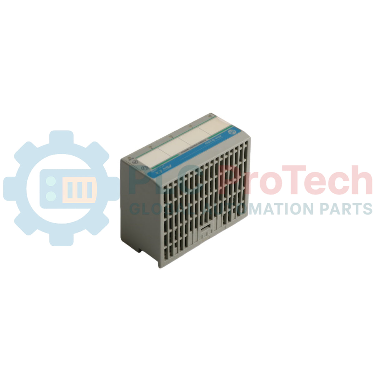
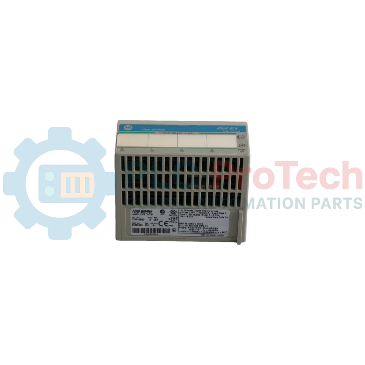
Allen-Bradley 1797-OB4D est un module de sortie numérique intrinsèquement sûr haute performance conçu pour les environnements industriels en zones dangereuses. Faisant partie de la famille de produits FLEX Ex I/O, ce module fournit 4 sorties non isolées en source spécifiquement conçues pour faire fonctionner des dispositifs numériques de terrain tels que vannes, alarmes sonores et solénoïdes.
Le module dispose d'une interface de communication FlexBus intégrée qui communique parfaitement via des adaptateurs compatibles comme l'adaptateur ControlNet Ex (1797-ACNR15) pour réaliser un mécanisme robuste à deux niveaux d'état de défaut sur le backplane. Ce produit est fourni en équipement de type ouvert et doit être installé sur une unité de base de bornier intrinsèquement sûre 1797-TB3 ou 1797-TB3S dans un boîtier approprié, garantissant une sécurité maximale du système et une isolation environnementale.
L'architecture électrique intègre des indicateurs de diagnostic et des profils de configuration logicielle sophistiqués accessibles via RSLogix 5000. Chaque canal en source est électriquement connecté aux autres et comprend une protection électronique avancée ainsi qu'un filtrage d'alarme sélectionnable, ce qui en fait un choix idéal pour les industries pétrochimiques, chimiques, gazières et les processus automatisés opérant en Zones 1, 2 ou 22.
Caractéristiques
Équipé de 4 sorties numériques intrinsèquement sûres, non isolées et en source.
Conçu pour le remplacement à chaud, permettant un retrait et une insertion sûrs sous tension en conditions non dangereuses.
Capacités complètes de diagnostic individuel des canaux incluant la détection de défaut de fil déconnecté et de surcharge.
Filtre intégré configurable par logiciel à 100 Hz (10 ms) et constantes de temps de filtre d'alarme réglables (0,25 ms à 32 ms).
Comportements de défaut de sortie sélectionnables permettant aux canaux de se réinitialiser à zéro ou de maintenir le dernier état valide.
Diagnostic physique clair avec 4 indicateurs d'état jaunes, 4 indicateurs de défaut rouges et 1 indicateur d'alimentation du module vert.
Protection électronique intégrée couvrant la rupture de fil, les conditions de surcharge et les courts-circuits.
Conception à semi-conducteurs utilisant une connectivité standard FlexBus avec une inductance interne négligeable.
Applications
Contrôle automatisé de vannes pneumatiques et hydrauliques intrinsèquement sûres.
Contrôle et déclenchement d'alarmes sonores et de balises visuelles montées sur le terrain dans des zones explosives.
Actionnement de solénoïdes basse puissance et de bobines de relais dans des atmosphères de gaz ou de poussières dangereuses.
Déploiement d'automatisation des processus dans les usines de traitement chimique, les raffineries de pétrole et les installations en amont du gaz.
Gestion sécurisée des signaux dans les environnements de manutention de grains ou de traitement de poudres répondant aux critères de poussière de la Zone 22.
Spécifications techniques
Attribut
Valeur
Fabricant
Allen-Bradley / Rockwell Automation
Modèle
1797-0B4D
Série de produits
FLEX Ex I/O
Nombre de sorties
4, non isolées, sourcing
Type de sortie IS
Ex ia IIB/IIC T4, AEx ia IIC T4, Classe I, II, III Division 1 Groupes A, B, C, D, E, F, G T4
Type de module IS
Ex ib IIB/IIC T4, AEx ib IIC T4, Classe I Division 1 Groupes A...D T4
Plage de charge
Plage de charge 30...5000 Ohm
Détection de défaut
Bits de défaut dans le tableau de données et LED (par canal) clignotant rouge (1 Hz)
Protection électronique
Rupture de fil, surcharge, court-circuit
Temps de retard maximal de sortie (arrêt à marche)
<1,2 ms
Temps de retard maximal de sortie (marche à arrêt)
<1,2 ms
Indicateurs
4 indicateurs d'état jaunes, 4 indicateurs de défaut rouges, 1 indicateur d'alimentation du module vert
Paramètres de sortie (intrinsèquement sûre)
Ui < 5,8 V CC, Ii < 400 mA, Li = négligeable, Ci < 1,35 µF
Type d'alimentation
Alimentation intrinsèquement sûre +V, -V
Paramètres d'alimentation
Ui < 9,5 V CC, Ii < 1 A, Li = négligeable, Ci = négligeable
Consommation électrique côté terrain du module
7,5 W
Dissipation de puissance
5 W
Dissipation thermique
17,07 BTU/h
Emplacement du module
Unité de base de bornier 1797-TB3 ou 1797-TB3S
Taille maximale des fils conducteurs
Conducteurs 4 mm2 (calibre 12) multibrins avec isolation de 1,2 mm (3/64 in)
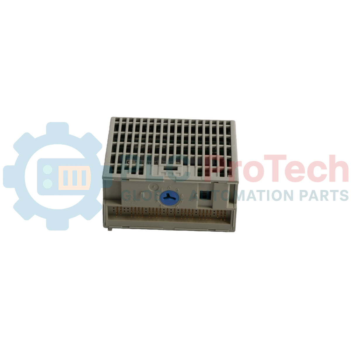
Position de l'interrupteur à clé
Position 7
Température de fonctionnement
-20...+70 °C (-4...+158 °F)
Température de stockage
-40...+85 °C (-40...+185 °F)
Humidité relative
5...95 % sans condensation
Choc en fonctionnement / hors fonctionnement
Testé à une accélération de pointe de 15 g, largeur d'impulsion 11(+1) ms
Vibration
Testé à 2 g @ 10...500 Hz selon IEC68-2-6
Dimensions (H x L x P)
46 x 94 x 75 mm (1,8 x 3,7 x 2,95 in)
Poids
Environ 200 g (7,05 oz)
Connexions/Interfaces
Broche de la borne
Fonction
Rangée A - Borne 0
Connexion de sortie canal 0 (+)
Rangée A - Borne 1
Connexion de sortie canal 0 (-)
Rangée A - Borne 4
Connexion de sortie canal 1 (+)
Rangée A - Borne 5
Connexion de sortie canal 1 (-)
Rangée A - Borne 8
Connexion de sortie canal 2 (+)
Rangée A - Borne 9
Connexion de sortie canal 2 (-)
Rangée A - Borne 12
Connexion de sortie canal 3 (+)
Rangée A - Borne 13
Connexion de sortie canal 3 (-)
Rangée C - Borne 34
Entrée d'alimentation intrinsèquement sûre +V CC
Rangée C - Borne 35
Entrée commune d'alimentation intrinsèquement sûre -V CC
Rangée C - Borne 50
Borne d'extension en chaîne en série +V CC
Rangée C - Borne 51
Borne d'extension en chaîne en série commune -V CC
Remarque : Les bornes 2, 3, 6, 7, 10, 11, 14, 15, 17 à 32, 36, 37, 38, 39, 46, 47, 48 et 49 ne sont pas utilisées et aucune connexion n'est permise. N'utilisez pas les bornes inutilisées comme bornes de support pour éviter d'endommager le système.
Directives d'installation
Spécifications de l'enceinte : Le module doit être installé dans une enceinte métallique adéquatement classée lorsqu'il est utilisé en Zone 1 afin de le protéger de l'exposition environnementale, car le module lui-même possède un indice de protection IP20.
Sélection de l'armoire Zone 22 : Pour une installation dans des environnements poussiéreux de la Zone 22, des modèles d'armoires certifiés spécifiques doivent être utilisés : IVK-ISRPI-V16LC, IVK-ISRPI-V8HYW ou IVK-ISRPI-V8LC.
Alignement du commutateur à clé : Avant de monter le module, tournez le commutateur à clé sur l'unité de base du bornier dans le sens horaire jusqu'à la position 7. Ne modifiez pas ce réglage du commutateur à clé une fois la configuration du câblage terminée.
Configuration FlexBus : Assurez-vous que le connecteur FlexBus est poussé complètement vers la gauche, en direction de l'unité de base ou de l'adaptateur voisin, avant d'essayer d'insérer le module ; l'exécution est bloquée si le connecteur n'est pas entièrement étendu.
Alignement et insertion des broches : Vérifiez que toutes les broches de connexion inférieures sont droites, alignez la barre d'alignement du module avec la rainure d'alignement de la base, puis appuyez fermement jusqu'à ce que le mécanisme de verrouillage s'enclenche solidement.
Séparation à sécurité intrinsèque : Ne reliez que des bases de bornier à sécurité intrinsèque à d'autres modules/adaptateurs du système à sécurité intrinsèque pour garantir l'intégrité du backplane.
Blindage et mise à la terre : Tout câblage E/S doit utiliser un fil blindé de haute qualité. Tous les blindages de fil doivent être terminés strictement à l'extérieur du module en utilisant des barres omnibus dédiées ou des points de passage pour blindage.
Prévention électrostatique : L'ensemble du système doit être protégé contre les charges électrostatiques. Installez un panneau d'avertissement très visible à proximité immédiate indiquant : « ATTENTION Éviter la charge électrostatique ».
Restrictions d'alimentation : Le système doit être alimenté exclusivement par une alimentation à sécurité intrinsèque. Ne jamais appliquer de signaux non à sécurité intrinsèque au module, car cela invalide définitivement son statut de sécurité intrinsèque.
Règles d'insertion à chaud : Bien que le module supporte le retrait et l'insertion sous tension, un arc électrique peut se produire si la base de bornier sous-jacente est désengagée ou câblée alors que l'alimentation de terrain est active, ce qui présente un risque d'explosion dans les zones dangereuses. Assurez-vous que l'alimentation est complètement isolée ou que l'environnement est vérifié comme non dangereux avant toute manipulation.
Conformité et certifications
CENELEC : II (1) 2G Ex ib[ia] IIC T4, II (1) D [Ex iaD]
UL, C-UL : Certifié pour Classe I, Groupes A, B, C, D ; Classe II, Groupes E, F, G ; Emplacements dangereux Classe III ; Classe I, Zone 1, AEx ib[ia] IIC T4
FM : Sécurité intrinsèque Classe I, Div 1, Groupes A, B, C, D, T4 ; Appareils associés avec connexions à sécurité intrinsèque Classe I, II, III, Div 1, Groupes A-G ; Classe I, Zone 1, AEx ib[ia] IIC T4
INMETRO : BR-Ex ia/ib BB/IIC T4
IECEx : [Zone 0] Ex ib[ia] IIC T4 [Ex iaD] (Certificat de référence : IECEx BVS 09.0024X)
ATEX : Numéro de certificat de référence DMT 02 ATEX E 040 X conforme aux normes EN 60079-0, EN 60079-11, et série EN 61241
Directives CE : Approuvé pour l'installation dans les régions de l'UE et de l'EEE selon la directive CEM 2014/30/UE appliquant EN 61000-6-4:2007, EN 61000-6-2:2005, et EN 61326-1:2013
FAQ
Quelles bases de bornes sont compatibles avec le module 1797-OB4D ?
Le module doit être utilisé exclusivement avec les unités de base de bornes intrinsèquement sûres 1797-TB3 ou 1797-TB3S.
Que signifie une LED d'état rouge fixe sur le panneau avant ?
Un indicateur rouge fixe signifie que le module n'a pas réussi sa routine de vérification au démarrage.
Ce module peut-il être réparé si un seul canal tombe en panne ?
Non, ce module n'est pas réparable sur le terrain. Tenter d'ouvrir le boîtier annule la garantie d'usine et ses certifications de sécurité intrinsèque.
Quel est l'état de fonctionnement par défaut des sorties au démarrage initial ?
Au démarrage du système, le bit Activation de sortie est par défaut réglé à 0, ce qui maintient toutes les sorties forcées à l'arrêt jusqu'à ce qu'il soit initialisé à 1 via le programme applicatif.
Quelle plage de résistance de charge de terrain est prise en charge pour un fonctionnement normal ?
La plage normale de charge par canal est définie de 30 à 5000 Ohm.
Comment le module signale-t-il un défaut de fil déconnecté ou de surcharge de canal ?
Les défauts sont signalés via les bits de défaut de la table de données interne et par le clignotement de la LED du canal correspondant en rouge à une fréquence de 1 Hz.
Est-il sûr d'utiliser ce module avec des signaux standards non intrinsèquement sûrs ?
Non, vous ne devez jamais appliquer de signaux non intrinsèquement sûrs. Le module ne peut pas être réutilisé dans un environnement intrinsèquement sûr une fois exposé à des signaux non intrinsèquement sûrs.
Que se passe-t-il si je connecte des dispositifs de terrain aux bornes inutilisées de la base ?
Utiliser des bornes inutilisées comme bornes de support peut causer des dommages physiques graves au module, des opérations système non intentionnelles, ou les deux.
Quel est le temps maximal de propagation du signal pour les changements d'état des canaux ?
Le temps de retard maximal de sortie pour les transitions OFF-vers-ON et ON-vers-OFF est inférieur à 1,2 ms.
Les canaux de sortie sont-ils isolés les uns des autres ?
Non, les canaux de ce module ne sont pas isolés et sont électriquement connectés les uns aux autres.
Peut-on insérer ce module dans une base de bornes sous tension pendant que le backplane est alimenté ?
Oui, il est conçu pour le remplacement à chaud, mais l'alimentation côté terrain doit être coupée ou la zone vérifiée comme non dangereuse pour éviter une explosion due à un arc électrique.
Quel est le but du paramètre de configuration Verrouiller les alarmes ?
Il détermine si un bit de défaut de fil déconnecté ou de surcharge reste verrouillé jusqu'à ce qu'il soit manuellement effacé par une transition Réinitialiser les alarmes, garantissant que les défauts de courte durée sont capturés.
Quel seuil garantit qu'un défaut de fil déconnecté est signalé ?
Une condition de fil déconnecté est garantie d'être signalée et rapportée pour des charges de terrain supérieures à 75 kOhm, quel que soit l'état de sortie.
Comment les filtres d'alarme de défaut sont-ils configurés dans le logiciel ?
Les bits du filtre d'alarme permettent de régler la constante de temps parmi une gamme d'options binaires : 0,25 ms, 0,5 ms, 1 ms, 2 ms, 4 ms, 8 ms, 16 ms ou 32 ms.
Technical Datasheet (PDF)Complete specifications and technical drawings.
Expédition express mondiale
Livraison standard : 4 à 6 jours ouvrables via DHL, FedEx et UPS.
Expédition express : Expédition le jour même pour les commandes en stock passées avant 14h00 (GMT+8).
Couverture mondiale : Service dans plus de 150 pays, avec livraison rapide en Arabie Saoudite et aux Émirats Arabes Unis.
Retours et garantie
Garantie de 30 jours : Retours acceptés pour les produits en stock dans leur emballage d'origine scellé en usine.
Garantie de 12 mois : Chaque composant industriel est couvert par notre garantie technique professionnelle.
Les commandes sont traitées et livrées du lundi au vendredi (hors jours fériés).
Pour connaître l'éligibilité complète, les frais de restockage et les détails des retours internationaux, veuillez consulter notre site officiel
Politique de remboursement et de retour
.
Les données de maintenance relient les ordres de travail, les signaux des capteurs, l'historique des actifs, les coûts et les connaissances des techniciens. Bien utilisées, elles améliorent la...
Cet article explique comment les actionneurs électriques intégrés, tels que la série e-Actuator de SMC, transforment le contrôle de mouvement industriel en remplaçant les systèmes pneumatiques et...
Cet article explique comment les systèmes PLC réalisent les opérations mathématiques de base telles que l'addition, la soustraction, la multiplication, la division, le modulo et l'exponentiation dans...
L'article explique plusieurs fonctions avancées de logique booléenne utilisées en programmation d'automates programmables industriels (API) au-delà des opérations de base ET, OU et NON. Il couvre...
La logique booléenne est la base de tout programme PLC. Des commandes machines simples aux systèmes d'automatisation industrielle complexes, les portes logiques déterminent comment les contrôleurs...
Les pare-feux industriels jouent un rôle crucial dans la cybersécurité OT, protégeant les réseaux PLC, DCS et SCADA grâce à la segmentation, au contrôle des entrées/sorties et à l’intégration IDS/IPS...
Choisir une sélection entraîne un rafraîchissement complet de la page.