Présentation du Contrôle de Puissance Industriel
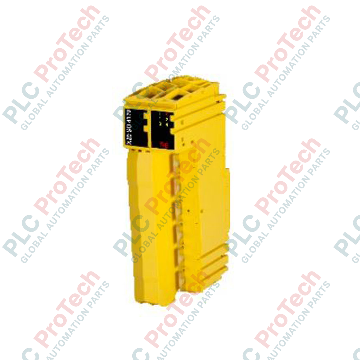
Le B&R 20SO4110 (20SO4110) est un module de sortie numérique industriel renforcé conçu pour la plateforme d'automatisation héritée B&R System 2005. Principalement déployé dans des secteurs de fabrication en fonctionnement continu tels que les machines d'extrusion de plastique, les systèmes de convoyeurs pour matériaux lourds et les commandes auxiliaires des centrales électriques traditionnelles, ce module gère des réseaux de commutation discrets à haute fiabilité. En s'interfaçant directement entre le processeur centralisé et les actionneurs de terrain (y compris les solénoïdes lourds, les bobines de relais d'interposition et les contacteurs magnétiques), le module assure une excellente isolation des signaux et une commutation rapide, protégeant ainsi le système contre les arrêts opérationnels.
Architecture de Sortie et Fiabilité Opérationnelle
Cette carte discrète présente une configuration haute densité optimisée pour une intégration sur backplane dans les racks standard System 2005. Les composants internes à semi-conducteurs sont conçus pour résister aux transitoires électriques industriels et aux fluctuations soudaines de charge typiques des ateliers. Construite avec un circuit dense et très durable, le module offre des capacités constantes de fourniture de courant sur tous les canaux actifs simultanément, éliminant les chutes de tension sur le bus de contrôle et garantissant des vitesses d'activation prévisibles pour le matériel de terrain en aval.
Matrice de Performance Technique
| Paramètre Matériel |
Détails de la Spécification |
| Modèle |
20SO4110 |
| Marque |
B&R (Plateforme System 2005) |
| Origine |
Autriche |
| Classification du Module |
Module de sortie numérique discret |
| Configuration E/S |
Sorties à semi-conducteurs multi-canaux |
| Compatibilité Système de Contrôle |
Automation Studio / Bus System 2005 |
| Température de Fonctionnement |
0 à 55 °C (Disposition standard en rack vertical) |
| Température de Stockage |
-25 à 85 °C |
| Plage d'Humidité Relative |
5 à 95 % (Sans condensation) |
| Poids Net |
0,45 kg |
| Poids Brut à l'Expédition |
2,0 kg (Emballage industriel lourd inclus) |
Intégration Système et FAQ
Quels sont les principaux indicateurs d'une défaillance matérielle de sortie sur le 20SO4110 ?
La face avant du 20SO4110 est équipée de LED de diagnostic dédiées pour le suivi de l'état des canaux. Si une commande active est envoyée depuis la logique du PLC mais que la LED du canal correspondant reste éteinte ou affiche un motif de défaut, vérifiez le fusible externe de terrain et confirmez que la ligne d'alimentation auxiliaire 24 VDC entrante est conforme aux tolérances standard.
Ce module peut-il être remplacé à chaud alors que le rack System 2005 est sous tension ?
Non. L'architecture du bus System 2005 exige que l'alimentation principale du backplane soit complètement coupée avant d'insérer ou de retirer toute carte E/S. Tenter de remplacer le 20SO4110 sous tension peut provoquer des arcs électriques entre les doigts dorés du backplane, entraînant des dommages matériels irréversibles au module ou aux cartes processeur adjacentes.
Comment gérer les canaux de sortie inutilisés dans le programme de contrôle ?
Les canaux inutilisés sur le 20SO4110 peuvent simplement rester déconnectés au niveau du bornier physique. Dans l'environnement logiciel (Automation Studio), ces canaux ne nécessitent pas de mappage ou de terminaison explicite, et les laisser non mappés ne déclenchera aucune erreur de bus backplane ni de diagnostic.
Mise en Service sur Site et Directives de Câblage
-
Suppression des Charges Inductives : Lors de l'utilisation des sorties pour piloter des charges inductives telles que des solénoïdes lourds, des embrayages mécaniques ou des contacteurs, installez des diodes de roue libre externes (pour circuits DC) ou des snubbers RC (pour circuits AC) directement aux bornes de la charge. Cette étape supprime les pics de tension inductifs à la source, prévenant la dégradation à long terme des interrupteurs à semi-conducteurs internes du module.
-
Propreté et Enclenchement du Backplane : Avant d'insérer le module dans l'emplacement System 2005, inspectez visuellement le connecteur du backplane pour détecter toute poussière ou particule en suspension. Insérez fermement le module dans le rack jusqu'à ce que les languettes de verrouillage mécaniques supérieure et inférieure s'enclenchent, assurant une connexion à faible résistance avec le bus logique.
-
Gestion Thermique de l'Enceinte : Assurez-vous que l'enceinte électrique maintient un flux d'air adéquat pour garder la température ambiante autour du rack en dessous de 55 °C. Maintenez un dégagement vertical minimum de 50 mm au-dessus et en dessous de la cage à cartes pour favoriser le refroidissement par convection naturelle et éviter les points chauds thermiques localisés.