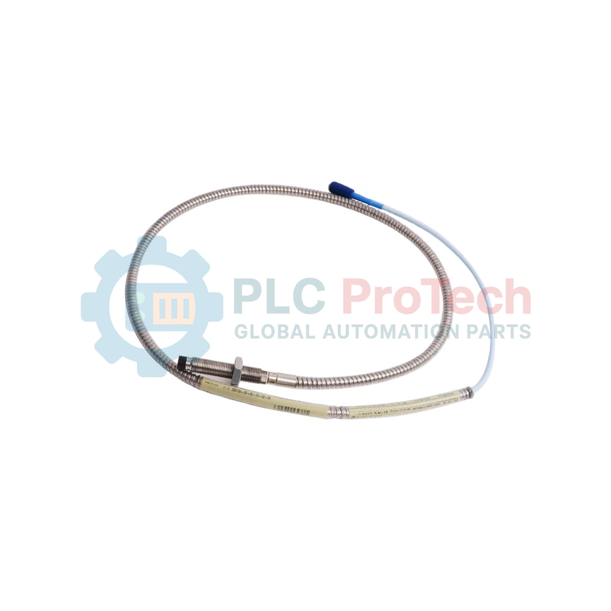
Description
Providing critical shaft dynamic displacement and position data for machinery protection systems, the Bently Nevada 330104-00-13-10-02-CN operates as a ruggedized non-contacting transducer within the 3300 XL 8mm Series. This proximity probe is specifically engineered to measure radial vibration, axial thrust, and phase reference on high-speed rotating shafts. Utilizing a highly resilient Polyphenylene sulfide (PPS) tip and an AISI 303/304 stainless steel threaded body, it maintains electrical and mechanical stability under severe operating conditions, such as those found in steam turbines, gas turbines, and large industrial compressors.
Key Features
-
Advanced Tip Protection: Molded Polyphenylene sulfide (PPS) tip resists chemical degradation, oil penetration, and high operating temperatures.
-
Robust Mechanical Design: Metric M10x1 thread configuration with 130mm overall case length for precise positioning inside tight machine housings.
-
ClickLoc Connector System: Equipped with a gold-plated miniature coaxial ClickLoc connector, preventing accidental disconnection while ensuring minimal signal attenuation.
-
High Stability Signal: Designed for seamless integration with 3300 XL Proximitor Sensors to achieve a standard 200 mV/mil (7.87 V/mm) linear scale factor.
-
CN Certification: Certified with country-specific hazardous area approvals for safe deployment in volatile industrial environments.
Applications
- Continuous radial vibration monitoring of fluid-film bearings.
- Thrust position measurements on critical turbomachinery.
- Speed sensing and Keyphasor phase reference tracking.
- Asset condition monitoring in petrochemical, power generation, and refining facilities.
Technical Specifications
| Parameter |
Specification Value |
| Manufacturer |
Bently Nevada (Baker Hughes) |
| Model Code |
330104-00-13-10-02-CN |
| Probe Series |
3300 XL 8 mm Proximity Probe |
| Thread Configuration |
Metric M10 x 1 (Standard Case) |
| Unthreaded Length Option |
00 (0 mm unthreaded portion) |
| Overall Case Length Option |
13 (130 mm overall case length) |
| Total Length Option |
10 (1.0 meter / 3.3 feet total cable length) |
| Connector and Cable Type |
02 (Miniature coaxial ClickLoc connector, standard cable) |
| Agency Approvals |
CN (Country-specific hazardous location and explosion protection) |
| Probe Tip Material |
Polyphenylene sulfide (PPS) |
| Probe Case Material |
AISI 303 or 304 Stainless Steel (SST) |
| Linear Range |
2.0 mm (80 mils), starting at approx 0.25 mm (10 mils) from target |
| System Sensitivity |
7.87 V/mm (200 mV/mil) when combined with standard AISI 4140 steel target |
| Operating Temperature Range |
-51 Celsius to +177 Celsius (-60 Fahrenheit to +350 Fahrenheit) |
| Country of Origin |
United States (U.S.A.) |
| Shipping Weight (Calculated) |
2.00 kg (with industrial packaging) |
Connections and Interfaces
| Connection Component |
Interface & Function |
| Coaxial Center Pin |
Transmits high-frequency RF signal from the Proximitor; carries dynamic AC/DC voltage feedback. |
| Outer ClickLoc Collar |
Common/Shield return line. Provides physical mechanical locking and environmental sealing. |
| M10 Threaded Body |
Rigid physical ground connection to the machine housing when locked with a structural jam nut. |
Empirical Engineering Insights
Alternative Models & Compatibility
The 1.0-meter probe system must always be paired with a corresponding 3300 XL extension cable (either 4.0 meters or 8.0 meters) to match the calibration path of 5.0-meter or 9.0-meter Proximitor systems. Connecting a 1.0-meter probe directly or using incorrect cable lengths will result in severe calibration errors and incorrect displacement measurements. If replacing an older, non-XL 3300 probe, verify that the Proximitor has been upgraded, as mismatching XL and non-XL components degrades linear tracking performance.
Application Pitfalls & Engineering Notes
Ensure that the mounting location has a minimum clearance of 40 mm (1.6 inches) diameter of flat surface around the probe tip to prevent side-loading. Side-loading, caused by the proximity of adjacent structural metal, creates parasitic magnetic fields that shift the baseline gap voltage. Additionally, check that the target material is AISI 4140 steel; other alloys will alter the nominal 200 mV/mil scale factor and require custom calibration curves.
Commissioning & Wiring Tips
When connecting the miniature coaxial ClickLoc connector, align the interfaces and press firmly together until the dynamic connection clicks into place. Avoid using pliers or heavy mechanical wrenches on the connector housing, as over-tightening or crushing the thin-wall connector destroys the gold-plated contact pins. Use silicone connector boot assemblies if the connection is directly exposed to synthetic turbine oil or solvent sprays.
Installation Guidelines
CRITICAL WARNING: De-energize the monitoring system and isolate the rotating machinery prior to installing or adjusting the proximity probe. High electrostatic charges or stray voltages in the turbine housing can cause equipment damage or ignition risks in explosive environments. Always verify area safety permits before opening junction boxes.
-
1
Inspect the M10 machine threads to ensure they are clean, dry, and free of metallic debris that could cause galling.
-
2
Thread the probe into the mounting bracket or sleeve while tracking the gap voltage using a calibrated multimeter hooked to the Proximitor OUT and COM terminals. Adjust physical depth until the voltage reads approximately -10.0 Vdc (the linear midpoint).
-
3
Lock the probe in place by tightening the external jam nut. Torque the locknut to the recommended OEM specification without shifting the probe body.
-
4
Route the coaxial cable through structural protective conduit to avoid physical abrasion or EMI noise coupling from power cables. Secure the ClickLoc connection to the extension cable and wrap with self-amalgamating tape if oil exposure is expected.