1 dari 3

Mitsubishi Electric GCU08CB-130 80173-109-01-3 GCT Thyristor Unit

Mitsubishi Electric GCU08CB-130 80173-109-01-3 GCT Thyristor Unit

Hanya 7 item tersisa di stok
  • Produsen: Mitsubishi Electric

  • Nomor Produk: GCU08CB-130 80173-109-01-3

  • Negara asal:Amerika Serikat

  • Jenis Produk: GCT Thyristor Unit

  • Kode batang: 8537101190

  • Pembayaran: T/T, Western Union

  • Berat: 1140g

  • Dimensi: 25cm x 20.7cm x 5.5cm

  • Pelabuhan pengiriman: Xiamen

  • Garansi: 12 bulan

Jumlah
Lihat detail lengkap

Description

The Mitsubishi Electric GCU08CB-130 is a symmetrical, high-power GCT (Gate Commutated Turn-off) Thyristor Unit integrated with an onboard gate driver. This press-pack semiconductor device features a specialized internal circuit board marked under reference code 80173-109-01-3. It is engineered explicitly for demanding switching actions in current source inverters, heavy-duty DC choppers, induction heating networks, and high-capacity DC to DC power converters. By permanently binding the GCT component to its gate driver on a unified motherboard, the assembly significantly reduces stray circuit loop inductance, ensuring rigid gate pulse synchronization and highly repetitive controllable off-state handling in modular industrial drive frameworks.

Features

  • Seamlessly combines a high-voltage GCT thyristor device with a matched gate driver on a direct-coupled motherboard assembly to eliminate external wiring loop inductance.
  • Implements robust electrical isolation via an optical fiber data link infrastructure utilizing standard Broadcom transceivers for control pulses.
  • Equipped with physical onboard troubleshooting infrastructure including a green power supply validation LED, a green gate indicator LED, and precise signal test points.
  • Utilizes a highly ruggedized press-pack structural casing optimized for clean mechanical mounting pressure alignment and uniform thermal heat sink interfacing.

Applications

  • High-power current source inverters and industrial drive systems.
  • Industrial DC choppers and multi-rail voltage step-conversion units.
  • High-frequency industrial induction heaters and metallurgical processing power panels.

Technical Specifications

Parameter Specification
Manufacturer Mitsubishi Electric Corporation
Model Number GCU08CB-130
Internal Motherboard Reference Code 80173-109-01-3
Product Classification
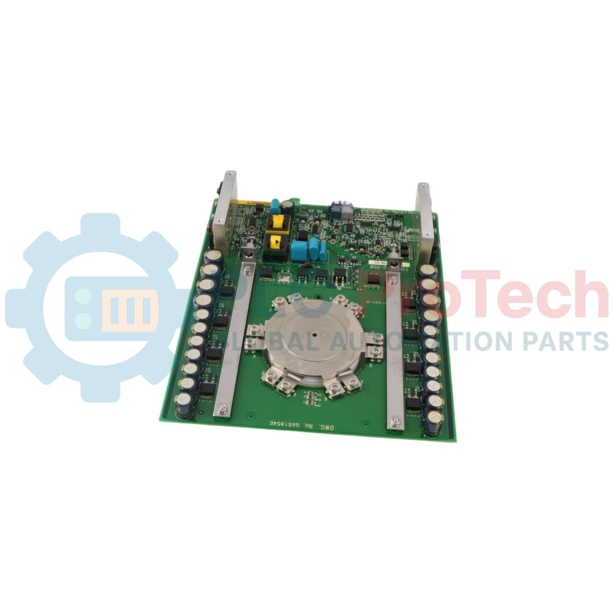
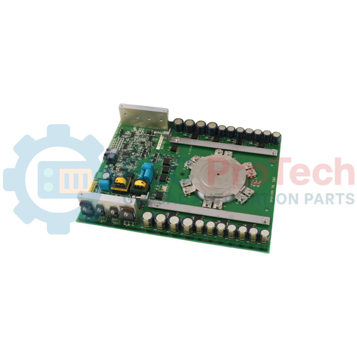
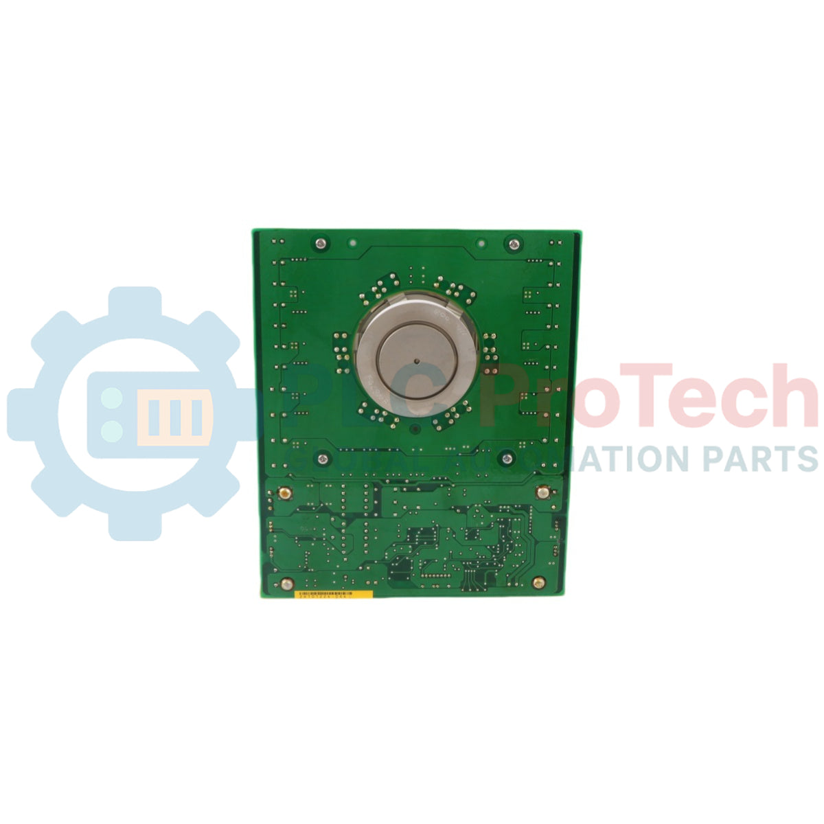
 GCT Thyristor Unit
Housing Construction Type Press Pack Type
Repetitive Peak Reverse Voltage (VRRM) 6500 V
Non-Repetitive Peak Reverse Voltage (VRSM) 6500 V
Repetitive Peak Off-State Voltage (VDRM) 6500 V
Non-Repetitive Peak Off-State Voltage (VDSM) 6500 V
Long Term DC Stability Voltage (V(LTDS)) 3600 V
RMS On-State Current (IT(RMS)) 800 A
Average On-State Current (IT(AV)) 520 A maximum (330 A nominal)
Repetitive Controllable On-State Current (ITQRM) 800 A
Surge On-State Current (ITSM) 4.8 kA maximum
Current-Squared, Time Integration Max Value (I2t) 7.6 x 10^4 A^2s
Critical Rate of Rise of On-State Current (diT/dt) 1000 A/microsecond
Critical Rate of Rise of Reverse Recovery Current (diR/dt) 1000 A/microsecond
Peak Forward Gate Power Dissipation (PFGM) 5 kW
Peak Reverse Gate Power Dissipation (PRGM) 17 kW
Average Forward Gate Power Dissipation (PFG(AV)) 100 W
Average Reverse Gate Power Dissipation (PRG(AV)) 120 W
Peak Forward Gate Voltage (VFGM) 10 V
Peak Reverse Gate Voltage (VRGM) 21 V
Peak Forward Gate Current (IFGM) 500 A
Peak Reverse Gate Current (IRGM) 800 A
Gate Driver Power Supply Input Voltage (VGIN) 20 V DC nominal (19 - 21 V DC acceptable window)
Gate Driver Power Consumption (PGIN) 35 W
Mechanical Clamping Force Requirement (FM) 11.1 to 15.8 kN (13 kN nominal benchmark)
Thyristor Pole Piece Diameter 47 mm
Assembly Housing Total Thickness 26 mm
Net Structural Weight 1060 g
Junction Operating Temperature Window (Tj) -20 to 125 Celsius
Ambient Storage Temperature Range (Tstg) -40 to 60 Celsius
Ambient Operating Temperature Bounds (Ta) -10 to 60 Celsius (Recommended threshold: <= 40 Celsius)
Thermal Resistance Junction-to-Fin (Rt(j-f)) 0.025 K/W

Connections/Interfaces

Port Component Identifier Interface Mapping / Engineering Function
Power Supply Connector Phoenix Contact Type MSTB25/2-G-5.08 plug-in port for 20 V DC gate driver power entry
Fiber Optic Input Port HFBR-2521Z Broadcom Optical Receiver for control pulse entry
Fault Signal Output Port HFBR-1521Z Broadcom Optical Transmitter for system response mapping
GATE TEST POINT Onboard probe node for real-time gate voltage diagnosis
CATHODE TEST POINT Onboard probe node mapping the cathode electrical reference return
LED A (Green) Visual confirmation status showing Power Supply OK
LED B (Green) Visual confirmation status mapping Gate conditions

Installation Guidelines

  • Clamping Pressure Execution: Install the unit within a calibrated compression rig ensuring a steady mechanical mounting force within the 11.1 kN to 15.8 kN range to establish proper electrical contact and minimize internal interface thermal resistance.
  • Fiber Link Protection: Keep the Broadcom HFBR-2521Z and HFBR-1521Z optical headers clean and free of contamination. Avoid tight component wiring bends to prevent control command signal attenuation.
  • Gate Supply Limits: Wire a regulated auxiliary DC supply ensuring voltage remains within the 19 to 21 V DC bounds directly at the board's two-pin connector plug to avoid driver switching delay anomalies.
Loading product navigation…
Key Features:

Product Documentation

Technical Datasheet (PDF) Complete specifications and technical drawings.

Technical Datasheet

Mitsubishi Electric GCU08CB-130 80173-109-01-3 GCT Thyristor Unit

What is the relationship between model GCU08CB-130 and the number 80173-109-01-3?

The official commercial model of the complete GCT thyristor assembly is GCU08CB-130, whereas 80173-109-01-3 represents the specific factory internal artwork printing tracking number on the integrated gate driver circuit board.

What happens if the power feed to the gate driver connector varies outside the specified range?

The gate driver board requires a highly stable input voltage between 19 and 21 V DC. Operating outside these boundaries can destabilize switching timing and potentially lead to permanent semiconductor module breakdown.

What are the recommended environmental temperature boundaries for safe device operation?

The device operates safely across a junction temperature range of -20 to 125 Celsius, and an ambient operating temperature range of -10 to 60 Celsius, though keeping ambient temperatures at or below 40 Celsius is recommended for optimized longevity.

Pengiriman Ekspres Global

  • Pengiriman Standar: 4-6 Hari Kerja melalui DHL, FedEx, dan UPS.
  • Pengiriman Ekspres: Pengiriman pada hari yang sama untuk pesanan dalam stok yang dilakukan sebelum pukul 14:00 (GMT+8).
  • Cakupan Seluruh Dunia: Melayani lebih dari 150 negara, termasuk pengiriman cepat ke Arab Saudi dan UAE.

Pengembalian & Garansi

  • Jaminan 30 Hari: Pengembalian diterima untuk produk yang tersedia dalam stok dengan kemasan asli yang tersegel pabrik.
  • Garansi 12 Bulan: Setiap komponen industri didukung oleh garansi teknis profesional kami.

Pesanan diproses dan dikirimkan Senin-Jumat (tidak termasuk hari libur nasional).


Untuk kelayakan penuh, biaya pengisian ulang, dan detail pengembalian internasional, silakan lihat resmi kami Kebijakan Pengembalian & Pengembalian Dana .

TECHNICAL SPECIFICATIONS

Color pattern
Hijau
Country of origin
Amerika Serikat
Power source
Daya DC

Produk yang Baru Dilihat

Pengetahuan teknis

Aktuator Listrik yang Dirancang untuk Menggantikan Sistem Tenaga Fluida: Panduan Praktis Otomasi Industri

Artikel ini menjelaskan bagaimana aktuator listrik terintegrasi, seperti seri e-Actuator dari SMC, mengubah kontrol gerak industri dengan menggantikan sistem pneumatik dan hidrolik tradisional....

Operasi Matematika Menggunakan OpenPLC untuk Aplikasi Otomasi Industri

Artikel ini menjelaskan bagaimana sistem PLC melakukan operasi matematika inti seperti penjumlahan, pengurangan, perkalian, pembagian, modulo, dan perpangkatan dalam otomasi industri. Artikel ini...

Logika Boolean Lanjutan dengan Pemrograman FBD PLC: Aplikasi Industri Praktis di Luar Logika Dasar

Artikel ini menjelaskan beberapa fungsi logika Boolean lanjutan yang digunakan dalam pemrograman PLC selain operasi dasar AND, OR, dan NOT. Artikel ini membahas bagaimana alat seperti tabel...

Logika Boolean dalam Pemrograman PLC: Memahami Gerbang Logika FBD

Logika Boolean adalah dasar dari setiap program PLC. Dari kontrol mesin sederhana hingga sistem otomasi industri yang kompleks, gerbang logika menentukan bagaimana pengendali merespons perubahan...

Panduan Mendalam tentang Firewall Industri dan Segmentasi Jaringan OT

Firewall industri memainkan peran penting dalam keamanan siber OT, melindungi jaringan PLC, DCS, dan SCADA melalui segmentasi, kontrol masuk/keluar, dan integrasi IDS/IPS yang sesuai dengan prinsip...

Panduan Gripper Robotik: Dari Penanganan Halus hingga Otomasi Berat

Gripper robot modern berkembang melampaui rahang mekanis tradisional. Mulai dari sistem adhesif yang terinspirasi oleh cicak dan gripper lembut yang aman untuk makanan hingga alat gudang bertenaga...