Description
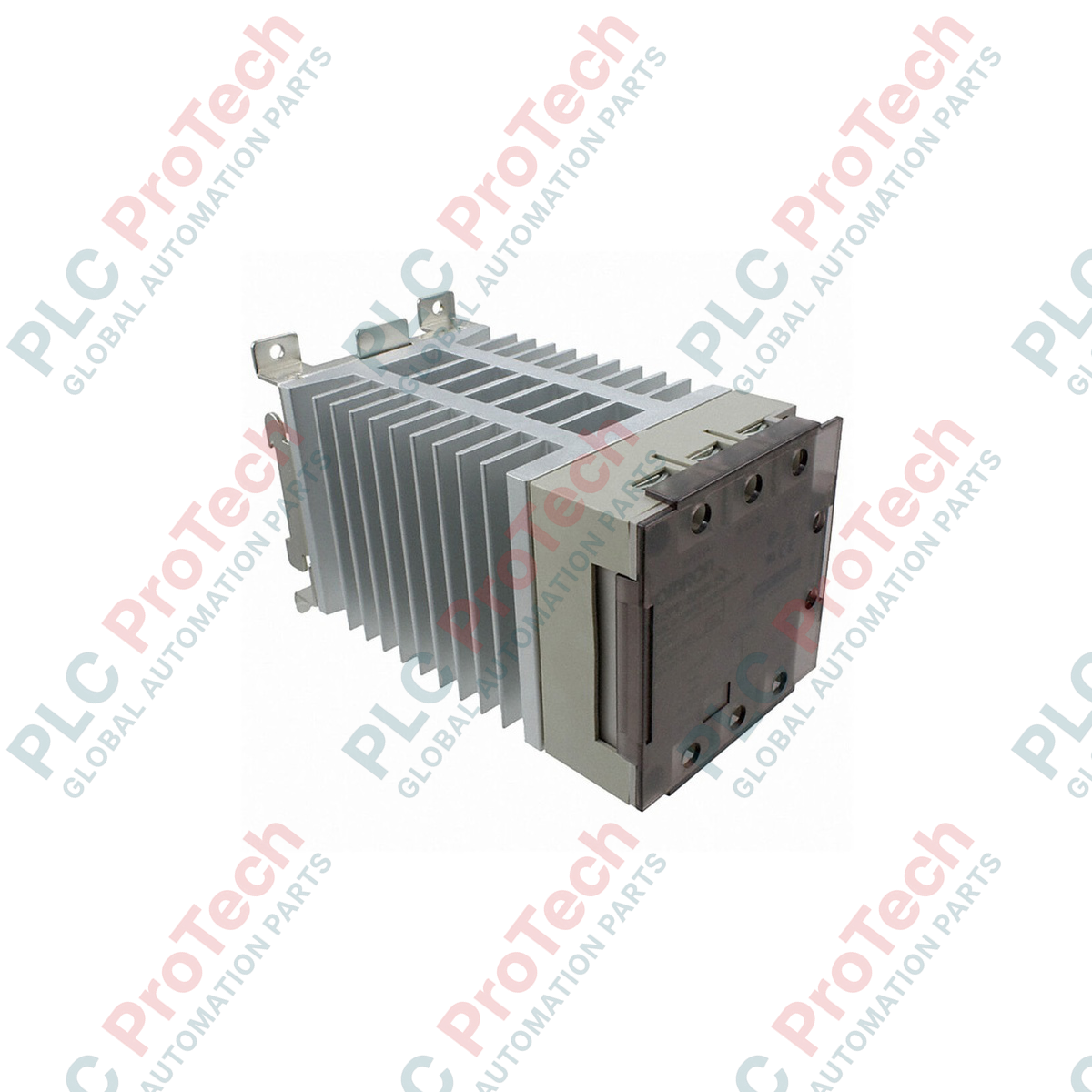
Engineered for precise industrial thermal regulation, the Omron G3PE-235B-2N facilitates highly efficient switching of three-phase heating loads up to 35 A. Utilizing a 2-phase switching topology, this device simplifies wiring in three-phase delta or star configurations without a neutral wire, providing a compact footprint inside electrical control panels. The integrated zero-cross function minimizes electromagnetic interference and electrical noise generation, safeguarding surrounding analog automation instrumentation during high-frequency cycling.
Features
-
Two-Phase Switching: Economical 2-element control configuration designed specifically for balanced 3-phase loads.
-
Zero Cross Function: Suppresses initial inrush currents and harmonic distortion by turning ON only when the AC voltage waveform crosses zero.
-
Phototriac Isolation: High-dielectric isolation barriers between low-voltage input control circuits and the power distribution grid.
-
Robust Overload Tolerance: High surge resistance rating designed to withstand short-duration high-current transients.
Applications
- Plastic extrusion and blow molding machine barrel heating.
- Semiconductor manufacturing chamber temperature maintenance.
- Industrial ovens, furnaces, and drying tunnels.
- Packaging heat-sealing bars and shrink wrap tunnel elements.
Technical Specifications
| Parameter |
Value |
| Manufacturer |
Omron |
| Model Code |
G3PE-235B-2N |
| Rated Input Control Voltage |
12 to 24 VDC |
| Operating Input Voltage Range |
9.6 to 30 VDC |
| Input Current |
10 mA maximum (at 24 VDC) |
| Rated Load Voltage |
100 to 240 VAC |
| Load Voltage Range |
75 to 264 VAC |
| Continuous Load Current |
35 A (at an ambient temperature of 40 degC) |
| Minimum Load Current |
0.5 A |
| Inrush Current Resistivity |
440 A (60 Hz, 1 cycle) |
| Permissible I2t Value |
1260 A2s |
| Load Capacity |
12.1 kW (at 200 VAC) |
| Isolation Method |
Phototriac |
| Terminal Type |
Screw terminals (with integrated terminal cover) |
| Mounting Style |
DIN-rail and panel surface mounting |
| Shipping Weight (Calculated) |
3.0 kg |
Connections and Interfaces
| Terminal Designation |
Function / Circuit Assignment |
| A1 / A2 (Input) |
Control DC voltage input (positive/negative terminals) |
| L1 / T1 (Output) |
Phase 1 AC power line input and load connection (Switched) |
| L2 / T2 (Output) |
Phase 2 AC power line input and load connection (Switched) |
| L3 / T3 (Output) |
Phase 3 direct bypass connection (Not switched internally, used for 2-phase control conduction path) |
Empirical Engineering Insights
Alternative Models & Compatibility
The "2N" designation specifies a 2-element (2-phase switching) module. If your application relies on a 3-element switching topology (e.g., systems containing grounded neutral star connections that require isolation on all lines), you must utilize the "3N" series variant instead. The physical mounting footprint and input terminal configurations remain identical between the two series, facilitating an easy mechanical upgrade path.
Application Pitfalls & Engineering Notes
Thermal management is the most critical factor for reliable SSR operation. When operating continuously at 35 A, the module must have unrestricted vertical convection airflow. If mounting multiple G3PE controllers side-by-side within an unventilated control panel, apply a derating factor of 10% to 20% to prevent thermal runaway. Ensure the heat sink fins remain clear of dust build-up.
Commissioning & Wiring Tips
Always use ring crimp terminals matching the screw terminal specs to ensure robust surface contact under thermal cycling. Under-tightened screw terminals will generate localized resistance-induced heat, leading to terminal housing degradation. To prevent damage from short-circuits on the load side, install fast-acting semiconductor fuses upstream of the SSR, sized to blow well below the internal 1260 A2s limit.
Installation Guidelines
CRITICAL WARNING: ELECTRICAL HAZARD
De-energize all primary load supply lines and auxiliary DC control supplies before undertaking installation, terminal adjustments, or inspection. Treat all heat sink structures as potentially hot during and directly following operation.
1
Mount the module vertically to a standard 35mm DIN rail or directly to a flat metal backplate using the mounting screws to optimize heat sink chimney-effect convection.
2
Ensure a minimum of 80mm free clearance directly above and below the device to allow proper airflow dissipation.
3
Apply the correct DC input control polarity (12 to 24 VDC) to terminals A1 (+) and A2 (-). Check polarity before energizing control circuits.
4
Secure load wiring to the output terminal blocks, ensuring torque meets Omron standard specifications for M4/M5 terminal screws to avoid high-contact-resistance hotspots.