


Replacing Yokogawa AAI835: Wiring and Barrier Checks Before Swap
Before replacing a Yokogawa AAI835, verify the 4-in/4-out channel map, power-loss loop behavior, barrier type, output load, cable, and redundancy.
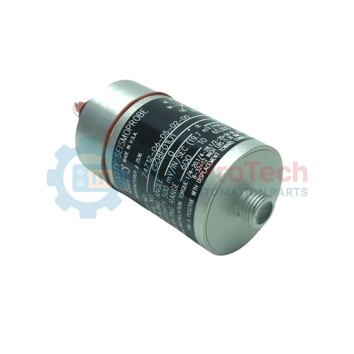
Manufacturer: Bently Nevada
Product No.: 74712-06-05-02-00
Country of origin:United States
Product Type: Trasduttori di velocità Seismoprobe
Payment: T/T, Western Union
Weight: 320g
Shipping port: Xiamen
Warranty: 12 months
Progettato per il monitoraggio continuo delle vibrazioni dei macchinari in condizioni termiche industriali impegnative, il Bently Nevada 74712-06-05-02-00 fornisce misurazioni precise della velocità del corpo sui macchinari rotanti critici. Questo trasduttore ad alta temperatura a due fili si basa sui principi di funzionamento della bobina mobile e genera una tensione proporzionale alla velocità di vibrazione senza richiedere alimentazione esterna. La configurazione specifica di questo modello 74712 Seismoprobe lo rende particolarmente adatto all'analisi delle vibrazioni strutturali su turbine a gas, turbine a vapore, pompe e ventilatori quando le temperature di esercizio superano i limiti dei sensori standard.
| Codice opzione | Tipo di opzione | Descrizione della configurazione selezionata |
|---|---|---|
| 06 | Angolo di montaggio / Frequenza operativa | 0° +/- 100°, frequenza operativa minima di 10 Hz (600 cpm) |
| 05 | Base di montaggio | Nessuna base; collegamento con prigioniero 1/2-20 UNF-3A |
| 02 | Opzione connettore | Montaggio superiore |
| 00 | Approvazione dell'ente | Nessuna approvazione |
| Produttore | Bently Nevada (Baker Hughes) |
| Serie del modello | Seismoprobe 74712 per alte temperature |
| Numero di parte completo | 74712-06-05-02-00 |
| Tipo di trasduttore | Sensore di velocità a bobina mobile autogenerante |
| Angolo di montaggio | 0° +/- 100° (orientamento di montaggio orizzontale) |
| Frequenza minima | 10 Hz (600 cpm) |
| Collegamento meccanico | Montaggio con prigioniero integrato 1/2-20 UNF-3A |
| Collegamento elettrico | Connettore multipolare montato superiormente |
| Certificazioni per aree pericolose | Nessuno (opzione 00) |
| Peso del trasduttore | 480 grammi (17 once) tipico |
| Peso di spedizione (calcolato) | 1,5 kg (3,3 libbre) |
La serie 74712 è una sostituzione specializzata per alte temperature dei sensori di velocità standard, come il Bently Nevada 9200. Assicurarsi che la configurazione del sistema di monitoraggio associato (ad es. Bently Nevada 3500/42M) corrisponda alle caratteristiche elettriche previste e ai valori di frequenza di taglio bassa del trasduttore 74712.
L'opzione "06" impone un vincolo sull'angolo di montaggio orizzontale. Il tentativo di installare questa unità verticalmente (90 gradi rispetto all'orizzontale) farà sì che la bobina mobile interna si posizioni fuori centro, causando clipping del segnale, errori di misurazione e usura meccanica interna prematura. Gli intervalli di temperatura di esercizio devono rimanere entro i limiti fisici dei gruppi interni del trasduttore per prevenire il deterioramento dell'isolamento della bobina.
Durante il passaggio dei cavi dal connettore con montaggio superiore, prevedere un'adeguata ansa di gocciolamento e uno scarico della trazione. Gli ambienti ad alta temperatura generano sollecitazioni meccaniche; pertanto, i cavi schermati e corazzati devono essere fissati saldamente a punti strutturali vicini, anziché essere lasciati pendere dalla testa del connettore.
Isolare la macchina e assicurarsi che si trovi in uno stato di energia zero prima di forare, maschiare o montare il sensore. Un urto fisico o una coppia eccessiva applicata direttamente al corpo del trasduttore durante l'installazione possono danneggiare permanentemente l'allineamento della bobina mobile interna.
Predisporre una superficie pulita e piana sull'alloggiamento del cuscinetto, perpendicolare all'asse di misurazione desiderato.
Verificare che la filettatura di montaggio corrisponda esattamente alla specifica del prigioniero 1/2-20 UNF-3A.
Applicare il frenafiletti se richiesto dalle specifiche dello stabilimento e serrare la base del trasduttore utilizzando esclusivamente le superfici piatte per la chiave. Non serrare afferrando il corpo del sensore.
Collegare il connettore con montaggio superiore e fissare la schermatura del cavo alla messa a terra designata del rack di monitoraggio per prevenire interferenze elettromagnetiche.

Global Express Shipping
Returns & Warranty


Global Express Shipping
Returns & Warranty
Orders are processed and delivered Monday-Friday (excluding public holidays).
For full eligibility, restocking fees, and international return details, please view our official Refund & Return Policy .
| Country of origin |
United States
|

Before replacing a Yokogawa AAI835, verify the 4-in/4-out channel map, power-loss loop behavior, barrier type, output load, cable, and redundancy.

ABB PM891K01 article 3BSE053241R1 is the non-redundant AC 800M processor kit. Use this field checklist before replacement.

Replacement checks for ABB TP853 3BSE018126R1: identify the installed CI853, CI855, CI857, or CI861 interface, record wiring, and verify communication after installation.

Engineering checks for the Allen-Bradley 5069-L330ERMS2: controller capacity, separate RTB kits, local I/O limits, network-node limits, and motion-axis count.

Checks to record before replacing ABB 3HNE 00006-1 DSQC 351: controller generation, X3/X5/X20/X21 wiring, DeviceNet settings, INTERBUS mapping, and LED states.

Compare the IC693CPU360 and IC693CPU364 by Ethernet interface, +5 VDC load, memory, rack limits, and replacement checks.