BECKHOFF

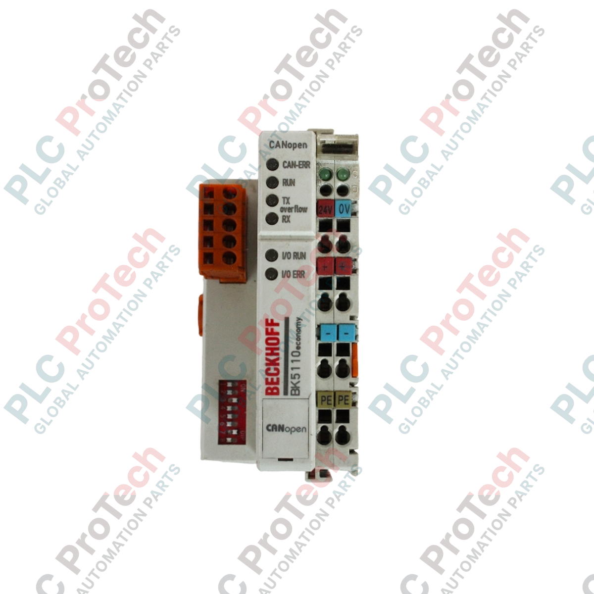
BECKHOFF BK5110 CANopen Bus Coupler

SKU BK5110

Disponibile
  • 12-month warranty
  • Free returns within 30 days
  • Manufacturer: BECKHOFF
  • Product No.: BK5110
  • Origin Germany
  • Product Type: CANopen Bus Coupler
  • Payment: T/T, Western Union
  • Weight: 0.13 kg
  • Shipping port: Xiamen
  • Warranty: 12 months

Tags

Quantità

Product Description

Description

The BECKHOFF BK5110 is a CANopen Bus Coupler designed to connect modular electronic terminal blocks to the CANopen fieldbus system. As a central node device, it translates high-level network communication from a CANopen master into the internal, fast K-bus signal structure used by connected Beckhoff Bus Terminals. This modular architecture allows the coupler to support up to 64 digital or analog signal terminals directly, expanding machine and system input/output capacity up to 256 digital inputs and outputs.

Equipped with an open-style 5-pin bus interface connector, the BK5110 facilitates flexible network topologies with data transfer rates up to 1 Mbaud. It features comprehensive CANopen protocol capabilities including variable mapping, node guarding, life guarding, emergency objects, and store/restore configuration functions. Configuration and parameterization can be performed directly via the integrated KS2000 software interface or through the network controller.

Features

  • Connects CANopen fieldbus networks to the modular BECKHOFF Bus Terminal system
  • Supports up to 64 Bus Terminals locally (expandable up to 256 inputs/outputs for digital signals)
  • Data transfer rates up to 1 Mbaud with automatic baud rate detection support
  • Configurable via KS2000 configuration software or the master controller
  • Extensive CANopen protocol feature set including variable mapping, node guarding, and emergency objects
  • Integrated 24 V DC power supply interface with internal K-bus current supply of 500 mA
  • Electrical isolation between power contacts and bus coupler supply voltage

Applications

  • Distributed industrial machine automation and modular production lines
  • CANopen-based factory floor data acquisition and sensor/actuator interfacing
  • Process control systems requiring modular digital and analog I/O expansion
  • Retrofitting and upgrading legacy machinery utilizing the CANopen communication standard

Technical Specifications

General

Parameter Specification
Manufacturer BECKHOFF
Exact Model BK5110
Product Type CANopen Bus Coupler
Number of Bus Terminals 64
Digital Peripheral Signals 256 inputs/outputs
Configuration Possibility via KS2000 or the controller

CANopen Communication

Parameter Specification
Bus Interface 1 x open style connector, 5-pin, included
Data Transfer Rates up to 1 Mbaud
Number of PDOs 5 Tx / 5 Rx
Additional Features life guarding, node guarding, emergency object, variable mapping, store/restore

Electrical

Parameter Specification
Power Supply 24 V DC (-15 % / +20 %)
Input Current 70 mA + (total K-bus current) / 4, 200 mA max.
Starting Current approx. 2.5 x continuous current
Recommended Fuse ≤ 10 A
Current Supply K-bus 500 mA
Power Contacts max. 24 V DC / max. 10 A
Electrical Isolation 500 V (power contact / supply voltage Bus Coupler)

Mechanical and Environmental

Parameter Specification
Weight approx. 130 g
Operating Temperature -25 to +60 degC
Storage Temperature -40 to +85 degC
Relative Humidity 95 %, no condensation
Vibration / Shock Resistance conforms to EN 60068-2-6 / EN 60068-2-27
EMC Immunity / Emission conforms to EN 61000-6-2 / EN 61000-6-4
Protection Class IP 20
Installation Position variable
Approvals CE, UL, Ex, GL

Connections / Interfaces

Interface Function
Bus Interface (5-pin open style connector) Connection to CANopen fieldbus network (CAN_H, CAN_L, CAN_GND, Shield, optional power)
Power Contacts Field supply feed for connected Bus Terminals (max. 24 V DC, max. 10 A)
K-bus Interface Internal high-speed communication link to modular Bus Terminals

Installation Guidelines

  1. Ensure the entire control system and field power supplies are fully de-energized before beginning mechanical installation or wiring work.
  2. Mount the BECKHOFF BK5110 Bus Coupler onto a standard 35 mm DIN rail alongside the required modular Bus Terminals, ensuring proper engagement of the internal K-bus sliding contacts.
  3. Connect the 24 V DC power supply to the designated terminals of the coupler, verifying correct polarity and ensuring the external fuse rating does not exceed 10 A.
  4. Connect the 5-pin open-style CANopen bus connector to the network cable, paying careful attention to proper shielding, grounding, and termination resistors according to CANopen physical layer guidelines.
  5. Verify all field-side power connections and potential distributions before restoring the 24 V DC supply voltage.
  6. Power on the system and check the diagnostic LED indicators on the coupler to confirm successful network association and operational readiness.
Shipping & Returns

Global Express Shipping

  • Standard Delivery: 4–6 business days via DHL, FedEx, and UPS.
  • Express Dispatch: Same-day dispatch for in-stock orders placed before 2:00 PM (GMT+8).
  • Worldwide Coverage: Serving over 150 countries.

Returns & Warranty

  • 30-Day Guarantee: Returns accepted for in-stock products in original, factory-sealed packaging.
  • 12-Month Warranty: Every industrial component is backed by our technical warranty.
FAQ
What is the primary function of the BECKHOFF BK5110?
The BECKHOFF BK5110 functions as a CANopen Bus Coupler that links external CANopen fieldbus networks with modular BECKHOFF Bus Terminals to control up to 256 digital peripheral signals.
How many Bus Terminals can be connected to the BECKHOFF BK5110?
The BECKHOFF BK5110 supports a maximum of 64 modular Bus Terminals directly on its internal K-bus extension.
What network data transfer rates does the BECKHOFF BK5110 support?
The BECKHOFF BK5110 supports CANopen data transfer rates of up to 1 Mbaud.
How is the BECKHOFF BK5110 configured?
The BECKHOFF BK5110 can be configured either via the integrated KS2000 software interface or directly through the master controller.
What power supply requirements does the BECKHOFF BK5110 need?
The BECKHOFF BK5110 requires a 24 V DC power supply (-15 percent / +20 percent) and provides an internal K-bus current supply of up to 500 mA.
Reviews

BK5110

Stock & lead time on request

Call
1 su 1

BECKHOFF BK5110 CANopen Bus Coupler

Only 10 item(s) left in stock
  • Manufacturer: BECKHOFF

  • Product No.: BK5110

  • Country of origin:Germany

  • Product Type: CANopen Bus Coupler

  • Payment: T/T, Western Union

  • Weight: 130g

  • Shipping port: Xiamen

  • Warranty: 12 months

Quantità
Visualizza dettagli completi

Product Description

Description

The BECKHOFF BK5110 is a CANopen Bus Coupler designed to connect modular electronic terminal blocks to the CANopen fieldbus system. As a central node device, it translates high-level network communication from a CANopen master into the internal, fast K-bus signal structure used by connected Beckhoff Bus Terminals. This modular architecture allows the coupler to support up to 64 digital or analog signal terminals directly, expanding machine and system input/output capacity up to 256 digital inputs and outputs.

Equipped with an open-style 5-pin bus interface connector, the BK5110 facilitates flexible network topologies with data transfer rates up to 1 Mbaud. It features comprehensive CANopen protocol capabilities including variable mapping, node guarding, life guarding, emergency objects, and store/restore configuration functions. Configuration and parameterization can be performed directly via the integrated KS2000 software interface or through the network controller.

Features

  • Connects CANopen fieldbus networks to the modular BECKHOFF Bus Terminal system
  • Supports up to 64 Bus Terminals locally (expandable up to 256 inputs/outputs for digital signals)
  • Data transfer rates up to 1 Mbaud with automatic baud rate detection support
  • Configurable via KS2000 configuration software or the master controller
  • Extensive CANopen protocol feature set including variable mapping, node guarding, and emergency objects
  • Integrated 24 V DC power supply interface with internal K-bus current supply of 500 mA
  • Electrical isolation between power contacts and bus coupler supply voltage

Applications

  • Distributed industrial machine automation and modular production lines
  • CANopen-based factory floor data acquisition and sensor/actuator interfacing
  • Process control systems requiring modular digital and analog I/O expansion
  • Retrofitting and upgrading legacy machinery utilizing the CANopen communication standard

Technical Specifications

General

Parameter Specification
Manufacturer BECKHOFF
Exact Model BK5110
Product Type CANopen Bus Coupler
Number of Bus Terminals 64
Digital Peripheral Signals 256 inputs/outputs
Configuration Possibility via KS2000 or the controller

CANopen Communication

Parameter Specification
Bus Interface 1 x open style connector, 5-pin, included
Data Transfer Rates up to 1 Mbaud
Number of PDOs 5 Tx / 5 Rx
Additional Features life guarding, node guarding, emergency object, variable mapping, store/restore

Electrical

Parameter Specification
Power Supply 24 V DC (-15 % / +20 %)
Input Current 70 mA + (total K-bus current) / 4, 200 mA max.
Starting Current approx. 2.5 x continuous current
Recommended Fuse ≤ 10 A
Current Supply K-bus 500 mA
Power Contacts max. 24 V DC / max. 10 A
Electrical Isolation 500 V (power contact / supply voltage Bus Coupler)

Mechanical and Environmental

Parameter Specification
Weight approx. 130 g
Operating Temperature -25 to +60 degC
Storage Temperature -40 to +85 degC
Relative Humidity 95 %, no condensation
Vibration / Shock Resistance conforms to EN 60068-2-6 / EN 60068-2-27
EMC Immunity / Emission conforms to EN 61000-6-2 / EN 61000-6-4
Protection Class IP 20
Installation Position variable
Approvals CE, UL, Ex, GL

Connections / Interfaces

Interface Function
Bus Interface (5-pin open style connector) Connection to CANopen fieldbus network (CAN_H, CAN_L, CAN_GND, Shield, optional power)
Power Contacts Field supply feed for connected Bus Terminals (max. 24 V DC, max. 10 A)
K-bus Interface Internal high-speed communication link to modular Bus Terminals

Installation Guidelines

  1. Ensure the entire control system and field power supplies are fully de-energized before beginning mechanical installation or wiring work.
  2. Mount the BECKHOFF BK5110 Bus Coupler onto a standard 35 mm DIN rail alongside the required modular Bus Terminals, ensuring proper engagement of the internal K-bus sliding contacts.
  3. Connect the 24 V DC power supply to the designated terminals of the coupler, verifying correct polarity and ensuring the external fuse rating does not exceed 10 A.
  4. Connect the 5-pin open-style CANopen bus connector to the network cable, paying careful attention to proper shielding, grounding, and termination resistors according to CANopen physical layer guidelines.
  5. Verify all field-side power connections and potential distributions before restoring the 24 V DC supply voltage.
  6. Power on the system and check the diagnostic LED indicators on the coupler to confirm successful network association and operational readiness.
Loading product navigation…

What is the primary function of the BECKHOFF BK5110?

The BECKHOFF BK5110 functions as a CANopen Bus Coupler that links external CANopen fieldbus networks with modular BECKHOFF Bus Terminals to control up to 256 digital peripheral signals.

How many Bus Terminals can be connected to the BECKHOFF BK5110?

The BECKHOFF BK5110 supports a maximum of 64 modular Bus Terminals directly on its internal K-bus extension.

What network data transfer rates does the BECKHOFF BK5110 support?

The BECKHOFF BK5110 supports CANopen data transfer rates of up to 1 Mbaud.

How is the BECKHOFF BK5110 configured?

The BECKHOFF BK5110 can be configured either via the integrated KS2000 software interface or directly through the master controller.

What power supply requirements does the BECKHOFF BK5110 need?

The BECKHOFF BK5110 requires a 24 V DC power supply (-15 percent / +20 percent) and provides an internal K-bus current supply of up to 500 mA.

Global Express Shipping

  • Standard Delivery: 4-6 Business Days via DHL, FedEx, and UPS.
  • Express Dispatch: Same-day dispatch for in-stock orders placed before 2:00 PM (GMT+8).
  • Worldwide Coverage: Serving over 150 countries, including rapid delivery to Saudi Arabia and UAE.

Returns & Warranty

  • 30-Day Guarantee: Returns accepted for in-stock products in original, factory-sealed packaging.
  • 12-Month Warranty: Every industrial component is backed by our professional technical warranty.

Orders are processed and delivered Monday-Friday (excluding public holidays).


For full eligibility, restocking fees, and international return details, please view our official Refund & Return Policy .

TECHNICAL SPECIFICATIONS

Country of origin
Germany

Technical knowledge

Tutto sui PLC: la CPU

A practical engineering guide to PLC CPU operation, from deterministic scan cycles and I/O image tables to memory, communications, diagnostics, redundancy, processor sizing, and reliable system...

Guida all’aggiornamento del firmware 1756-L73: scelta tra v19 e v21/v31

Sostituire un 1756-L73 non significa automaticamente aggiornare il firmware. Questa guida confronta le versioni 19.013, 21.011 e 31.011, concentrandosi sulla compatibilità dei progetti, sulle...

Implementazione della logica a scala XOR con 3 interruttori e bit interno

Implementa un circuito luminoso XOR con 3 interruttori SPST in LogixPro o RSLogix 500 utilizzando un bit di relè interno. Include tabelle della verità, equazioni booleane e verifica.

Creazione di una rete Modbus RTU con CompactLogix e DeltaV

Integra Allen-Bradley CompactLogix, Caterpillar ATS e generatori nel DCS DeltaV tramite Modbus RTU. Include i gateway ProSoft MVI69-MCM e Miille DIN266.

Istruzione ONS che non attiva l’OTE nella logica ladder di Studio 5000

L’istruzione ONS si attiva, ma la bobina OTE non rimane mai eccitata in Studio 5000 perché il one-shot è vero solo per una scansione. Usa OTL/OTU oppure una logica di autoritenuta.

Requisiti e topologia dello switch di rete EtherNet/IP Kinetix 5500

Configura i servoazionamenti Allen-Bradley Kinetix 5500 su EtherNet/IP. Include CIP Sync, la temporizzazione IEEE 1588 V2, la selezione degli switch Stratix, la topologia DLR e l’HMI.