


ABB PM891K01 Replacement: Check Redundancy Before Ordering
ABB PM891K01 article 3BSE053241R1 is the non-redundant AC 800M processor kit. Use this field checklist before replacement.
Manufacturer: BECKHOFF
Product No.: CP7901-0021-0000
Country of origin:Germany
Product Type: Pannelli di controllo industriali
Payment: T/T, Western Union
Weight: 500g
Shipping port: Xiamen
Warranty: 12 months
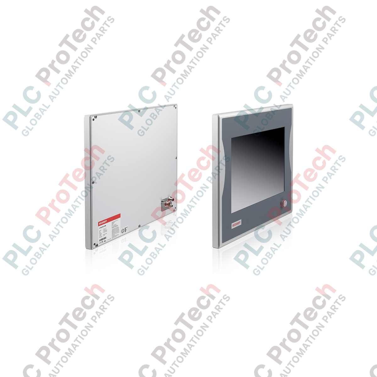
Fornendo un'interfaccia uomo-macchina robusta e salvaspazio per architetture di controllo distribuite, il Beckhoff CP7901-0021-0000 integra un display TFT ad alto contrasto da 12 pollici in un robusto involucro in alluminio con grado di protezione IP65. Questo pannello operatore utilizza la tecnologia integrata di estensione del segnale DVI-E e USB-E 2.0, consentendo una comunicazione fluida con un PC industriale host situato fino a 50 metri di distanza. Progettato specificamente per l'installazione su braccio di montaggio, questo dispositivo combina resistenza e visualizzazione ad alta fedeltà, risultando ideale per ambienti di produzione difficili che richiedono punti di controllo localizzati senza il carico di elaborazione locale.
| Parametro | Specifiche |
|---|---|
| Produttore | Beckhoff |
| Numero di modello / articolo | CP7901-0021-0000 |
| Dimensioni del display | Diagonale da 12 pollici |
| Risoluzione | 800 x 600 pixel |
| Materiale dell'involucro | Alluminio anodizzato, completamente chiuso |
| Grado di protezione | IP65 (tutte le direzioni) |
| Configurazione dell'interfaccia | DVI-E (DVI esteso) e USB-E 2.0 (USB esteso) |
| Lunghezza massima del cavo | Fino a 50 metri |
| Velocità di trasmissione USB | Fino a 480 Mbit/s |
| Ingresso alimentazione | 24 V CC |
| Temperatura di esercizio | Da 0 a 55 °C |
| Standard di montaggio | 4 fori filettati M6 x 18 mm sul pannello posteriore |
| Paese di origine | Germania |
| Peso di spedizione (calcolato) | 8,0 kg |
| Connettore / Porta | Funzione / Assegnazione |
|---|---|
| Ingresso DVI-E | Si collega all'uscita grafica del PC industriale tramite cavi di estensione compatibili con DVI-E standard. |
| Ingresso USB-E 2.0 | Si collega al controller USB del PC industriale tramite tecnologia di trasmissione a distanza estesa. |
| Connettore di alimentazione a 24 V CC | Interfaccia terminale sigillata per l'ingresso dell'alimentazione operativa (+24 V CC, 0 V, Terra). |
L'unità CP7901 è destinata specificamente all'uso con le schede trasmettitore Beckhoff (come CU8801 o CU8802) installate nell'armadio di controllo host. Non può essere collegata direttamente a una porta DVI/USB standard, non estesa, su lunghe distanze senza queste interfacce trasmettitore. In caso di sostituzione di vecchi moduli legacy CP7901 contenenti schede di estensione CC-Link o USB 1.1 personalizzate, assicurarsi che le revisioni firmware e hardware siano compatibili.
Quando si utilizza la portata massima di estensione di 50 metri, la stabilità del segnale dipende in larga misura dalla qualità dei cavi. Evitare di instradare le linee DVI-E e USB-E 2.0 attraverso percorsi ad alta interferenza contenenti cavi di alimentazione dei motori o uscite di inverter di frequenza. Se la comunicazione si interrompe a intermittenza, verificare che i cavi di estensione CAT5/CAT6 siano schermati e che la schermatura sia terminata correttamente a entrambe le estremità.
Collegare sempre a terra l'adattatore del braccio di montaggio direttamente al sistema principale di collegamento equipotenziale dell'impianto. I giunti meccanici standard del braccio possono compromettere la messa a terra nel tempo a causa dell'usura o dell'accumulo di lubrificante, causando potenzialmente sfarfallio dello schermo o interruzioni dell'input tattile dovuti a cariche elettrostatiche.
Montare l'involucro del pannello di controllo sull'adattatore per braccio di montaggio industriale utilizzando quattro viti M6 x 18 mm, assicurando un corretto ingaggio della filettatura e l'allineamento con la guarnizione in gomma.
Far passare i cavi DVI-E, USB-E e di alimentazione a 24 V CC designati attraverso il canale interno del sistema del braccio di montaggio, facendo attenzione a non superare il raggio di curvatura massimo dei cavi.
Inserire i cavi di alimentazione a 24 V CC nel connettore della morsettiera, verificando nuovamente la polarità corretta, quindi fissare saldamente il connettore all'alloggiamento.
Collegare i cavi DVI-E e USB-E. Prima di accendere il sistema, assicurarsi che tutti i passacavi e i connettori siano serrati correttamente per mantenere la tenuta ambientale IP65.

Global Express Shipping
Returns & Warranty
Global Express Shipping
Returns & Warranty
Orders are processed and delivered Monday-Friday (excluding public holidays).
For full eligibility, restocking fees, and international return details, please view our official Refund & Return Policy .
| Country of origin |
Germany
|

ABB PM891K01 article 3BSE053241R1 is the non-redundant AC 800M processor kit. Use this field checklist before replacement.

Replacement checks for ABB TP853 3BSE018126R1: identify the installed CI853, CI855, CI857, or CI861 interface, record wiring, and verify communication after installation.

Engineering checks for the Allen-Bradley 5069-L330ERMS2: controller capacity, separate RTB kits, local I/O limits, network-node limits, and motion-axis count.

Checks to record before replacing ABB 3HNE 00006-1 DSQC 351: controller generation, X3/X5/X20/X21 wiring, DeviceNet settings, INTERBUS mapping, and LED states.

Compare the IC693CPU360 and IC693CPU364 by Ethernet interface, +5 VDC load, memory, rack limits, and replacement checks.

A field-first diagnostic sequence for 1756-OF4 analog output problems: channel mode, removable terminal block, scaling, and controlled electrical checks.