


ABB PM891K01 Replacement: Check Redundancy Before Ordering
ABB PM891K01 article 3BSE053241R1 is the non-redundant AC 800M processor kit. Use this field checklist before replacement.
Manufacturer: BECKHOFF
Product No.: BK5110
Country of origin:Germany
Product Type: CANopen Bus Coupler
Payment: T/T, Western Union
Weight: 130g
Shipping port: Xiamen
Warranty: 12 months
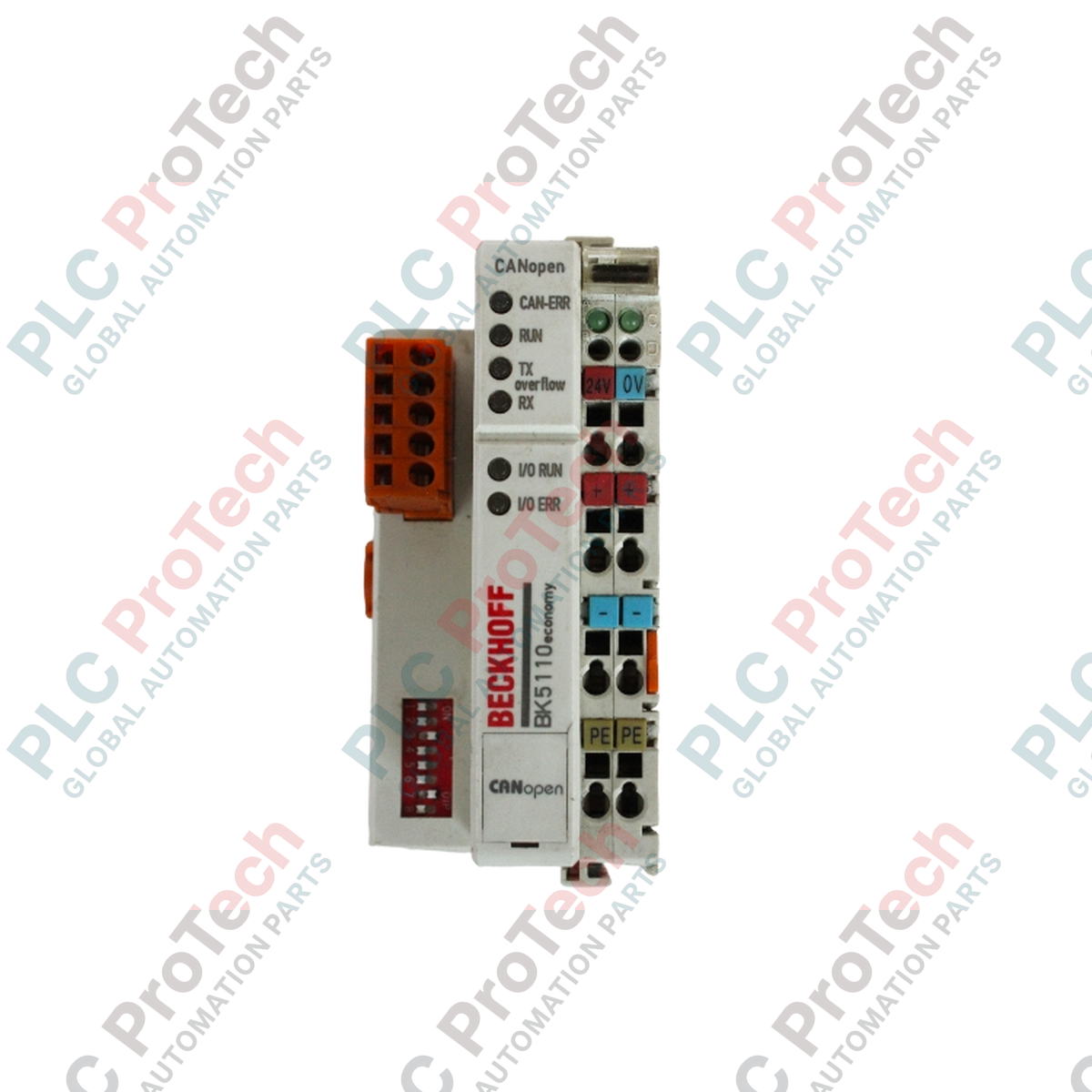
The BECKHOFF BK5110 is a CANopen Bus Coupler designed to connect modular electronic terminal blocks to the CANopen fieldbus system. As a central node device, it translates high-level network communication from a CANopen master into the internal, fast K-bus signal structure used by connected Beckhoff Bus Terminals. This modular architecture allows the coupler to support up to 64 digital or analog signal terminals directly, expanding machine and system input/output capacity up to 256 digital inputs and outputs.
Equipped with an open-style 5-pin bus interface connector, the BK5110 facilitates flexible network topologies with data transfer rates up to 1 Mbaud. It features comprehensive CANopen protocol capabilities including variable mapping, node guarding, life guarding, emergency objects, and store/restore configuration functions. Configuration and parameterization can be performed directly via the integrated KS2000 software interface or through the network controller.
| Parameter | Specification |
|---|---|
| Manufacturer | BECKHOFF |
| Exact Model | BK5110 |
| Product Type | CANopen Bus Coupler |
| Number of Bus Terminals | 64 |
| Digital Peripheral Signals | 256 inputs/outputs |
| Configuration Possibility | via KS2000 or the controller |
| Parameter | Specification |
|---|---|
| Bus Interface | 1 x open style connector, 5-pin, included |
| Data Transfer Rates | up to 1 Mbaud |
| Number of PDOs | 5 Tx / 5 Rx |
| Additional Features | life guarding, node guarding, emergency object, variable mapping, store/restore |
| Parameter | Specification |
|---|---|
| Power Supply | 24 V DC (-15 % / +20 %) |
| Input Current | 70 mA + (total K-bus current) / 4, 200 mA max. |
| Starting Current | approx. 2.5 x continuous current |
| Recommended Fuse | ≤ 10 A |
| Current Supply K-bus | 500 mA |
| Power Contacts | max. 24 V DC / max. 10 A |
| Electrical Isolation | 500 V (power contact / supply voltage Bus Coupler) |
| Parameter | Specification |
|---|---|
| Weight | approx. 130 g |
| Operating Temperature | -25 to +60 degC |
| Storage Temperature | -40 to +85 degC |
| Relative Humidity | 95 %, no condensation |
| Vibration / Shock Resistance | conforms to EN 60068-2-6 / EN 60068-2-27 |
| EMC Immunity / Emission | conforms to EN 61000-6-2 / EN 61000-6-4 |
| Protection Class | IP 20 |
| Installation Position | variable |
| Approvals | CE, UL, Ex, GL |
| Interface | Function |
|---|---|
| Bus Interface (5-pin open style connector) | Connection to CANopen fieldbus network (CAN_H, CAN_L, CAN_GND, Shield, optional power) |
| Power Contacts | Field supply feed for connected Bus Terminals (max. 24 V DC, max. 10 A) |
| K-bus Interface | Internal high-speed communication link to modular Bus Terminals |

Global Express Shipping
Returns & Warranty
Global Express Shipping
Returns & Warranty
Orders are processed and delivered Monday-Friday (excluding public holidays).
For full eligibility, restocking fees, and international return details, please view our official Refund & Return Policy .
| Country of origin |
Germany
|

ABB PM891K01 article 3BSE053241R1 is the non-redundant AC 800M processor kit. Use this field checklist before replacement.

Replacement checks for ABB TP853 3BSE018126R1: identify the installed CI853, CI855, CI857, or CI861 interface, record wiring, and verify communication after installation.

Engineering checks for the Allen-Bradley 5069-L330ERMS2: controller capacity, separate RTB kits, local I/O limits, network-node limits, and motion-axis count.

Checks to record before replacing ABB 3HNE 00006-1 DSQC 351: controller generation, X3/X5/X20/X21 wiring, DeviceNet settings, INTERBUS mapping, and LED states.

Compare the IC693CPU360 and IC693CPU364 by Ethernet interface, +5 VDC load, memory, rack limits, and replacement checks.

A field-first diagnostic sequence for 1756-OF4 analog output problems: channel mode, removable terminal block, scaling, and controlled electrical checks.