BECKHOFF

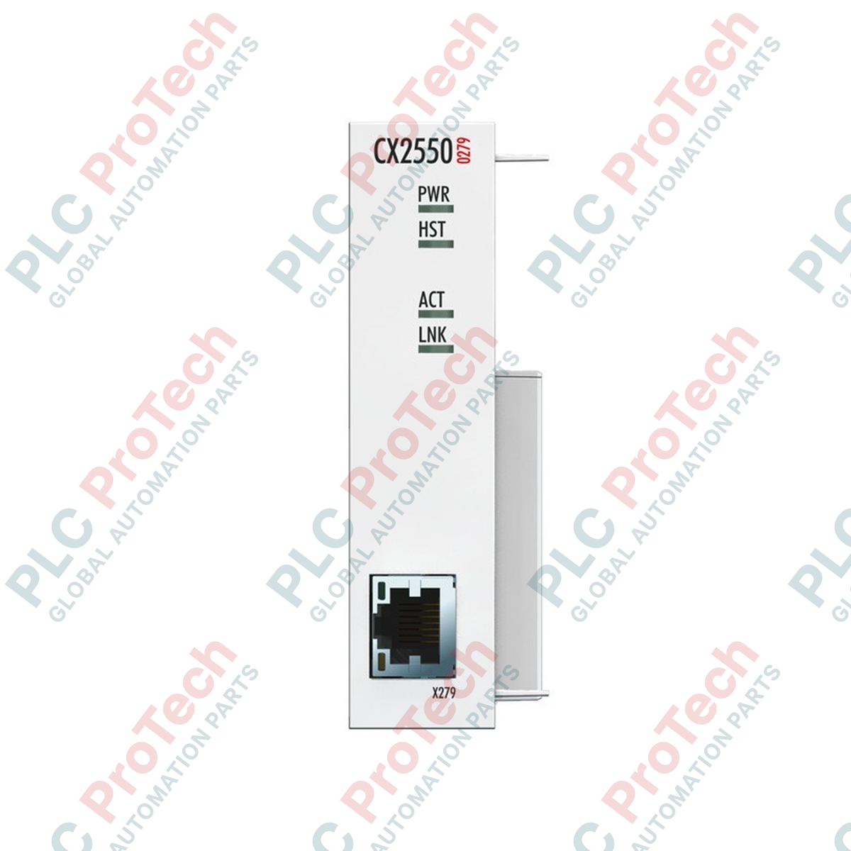
Beckhoff CX2550-0279 CX2000 Series USB Extender 2.0 Transmitter Module

SKU CX2550-0279

In stock
  • 12-month warranty
  • Free returns within 30 days
  • Manufacturer: BECKHOFF
  • Product No.: CX2550-0279
  • Origin Germany
  • Product Type: USB Extender Modules
  • Payment: T/T, Western Union
  • Weight: 0.5 kg
  • Dimensions: 24 mm x 99 mm x 54.5 mm
  • Shipping port: Xiamen
  • Warranty: 12 months

Tags

Quantity

Product Description

Description

The Beckhoff CX2550-0279 functions as a direct system-bus expansion module designed for CX20xx Embedded PCs, enabling remote USB 2.0 signal transmission up to 50 meters. This transmitter module mounts directly to the left-hand side of a CX20xx CPU block, converting standard internal USB lines into a serialized differential signal suitable for long-distance runs over standard Ethernet-style physical media. This setup is specifically optimized for connecting control panels such as the CP29xx-0000 series without signal degradation or latency spikes, ensuring seamless peripheral integration in complex industrial environments.

Key Features

  • Dedicated 1 x USB Extended 2.0 interface utilizing a rugged RJ45 connection port.
  • Reliable signal extension up to a maximum distance of 50 meters over standard Cat.5E or higher shielded cabling.
  • Native system bus integration drawing power directly through preceding CX2100-0xxx power supply units.
  • On-board LED diagnostic indicators for real-time status validation (Power, Host, Activity, and Link status).
  • Compact 24 mm form factor designed for high-density DIN-rail mounting configurations.

Applications

  • Connecting decentralized HMI and operator screens (CP29xx-0000 series) in scattered manufacturing cells.
  • Extending USB diagnostic interfaces outside enclosed, high-voltage electrical panels.
  • Facilitating clean wiring routing in modern modular production lines and material handling facilities.

Technical Specifications

Specification Parameter Technical Value
Manufacturer Beckhoff
Model Number CX2550-0279
Interface Type 1 x USB Extended 2.0 (via RJ45 socket)
Maximum Cable Length 50 meters (using Cat.5E cabling)
Power Feed Via system bus (through CX2100-0xxx modules)
LED Diagnostics Power (1x), Host (1x), Activity (1x), Link (1x)
Dimensions (W x H x D) 24 mm x 99 mm x 54.5 mm
Weight Approximately 190 g
Operating Temperature -25 to +60 degC
Storage Temperature -40 to +85 degC
Relative Humidity 95%, non-condensing
Protection Rating IP20
Vibration/Shock Resistance Conforms to EN 60068-2-6 / EN 60068-2-27
EMC Immunity/Emission Conforms to EN 61000-6-2 / EN 61000-6-4

Connections and Interfaces

Port Type Connector Pinout / LED Signal Description
RJ45 Output Port Pins 1 to 8 Differential USB transmission pairs over Cat.5E shielded line. Do not connect to Ethernet switches.
LED: PWR On (Green) Internal system power is successfully applied via the system bus.
LED: HOST On (Green) Established connection with the primary CX20xx CPU host interface.
LED: LINK On (Green) Active connection established with the remote CP29xx receiver.

Empirical Engineering Insights

Alternative Models & Compatibility

This module behaves specifically as a Point-to-Point Transmitter (Tx) and must be paired with an appropriate receiver, typically integrated directly into Beckhoff CP29xx-0000 Control Panels or external receiver boxes. It is physically designed to slide and snap into place on the left-side expansion slot of the CX20xx series. Ensure your CPU configuration in TwinCAT recognizes the additional module on the PC-system bus before commissioning.

Application Pitfalls & Engineering Notes

A common error on-site is treating the physical RJ45 interface on the front of this unit as an Ethernet network port. Patching this connection into a standard LAN switch, router, or hub can cause immediate electrical damage to either the network hardware or the internal transceiver circuitry of the controller. Keep the extension path strictly point-to-point.

Commissioning & Wiring Tips

For transmissions reaching near the 50-meter limit, always use high-quality, double-shielded copper cabling (S/FTP Cat.5E or Cat.6). Avoid routing this physical-layer run in close proximity to high-frequency variable frequency drive (VFD) output cables or high-voltage lines, as noise coupling on the differential lines can cause momentary dropouts in panel mouse/keyboard and touch signals.

Installation Guidelines

CRITICAL WARNING: Prior to snapping this expansion unit onto the CX20xx CPU module or altering any interface cables, ensure the entire controller rack and any connected remote displays are completely powered down. Verify that no residual voltages are present in the power supply line. Failure to de-energize can damage sensitive differential transceiver chips on the system bus.
1
Align the male multi-pin system-bus connector of the CX2550-0279 with the left-side female interface of the CX20xx CPU unit. Ensure the DIN-rail locking clips are pulled out.
2
Press the module firmly into place until you hear it click, securing it to the adjacent CPU module. Push the DIN-rail locking clips back in to anchor the module on the DIN rail.
3
Insert your dedicated Cat.5E shielded line into the front RJ45 socket and route directly to the panel receiver module, keeping it separate from high-interference power lines.
Shipping & Returns

Global Express Shipping

  • Standard Delivery: 4–6 business days via DHL, FedEx, and UPS.
  • Express Dispatch: Same-day dispatch for in-stock orders placed before 2:00 PM (GMT+8).
  • Worldwide Coverage: Serving over 150 countries.

Returns & Warranty

  • 30-Day Guarantee: Returns accepted for in-stock products in original, factory-sealed packaging.
  • 12-Month Warranty: Every industrial component is backed by our technical warranty.
FAQ
Can I connect this transmitter directly to a standard network switch or router?
No. The RJ45 interface uses a specialized proprietary physical layer to transmit differential USB signals. Connecting this port to an Ethernet switch or network device can damage the internal components of both units.
What is the maximum cable length supported by this module?
The module supports point-to-point connections up to a maximum distance of 50 meters. To reach this distance, use high-quality shielded Cat.5E or Cat.6 cabling.
Where does this module receive its operating power?
The device draws its power directly from the system bus connected to the adjacent CPU block, which is powered through standard CX2100-0xxx power supply units.
Reviews

CX2550-0279

Stock & lead time on request

Call
1 of 1

Beckhoff CX2550-0279 CX2000 Series USB Extender 2.0 Transmitter Module

Only 10 item(s) left in stock
  • Manufacturer: BECKHOFF

  • Product No.: CX2550-0279

  • Country of origin:Germany

  • Product Type: USB Extender Modules

  • Payment: T/T, Western Union

  • Weight: 500g

  • Dimensions: 24 mm x 99 mm x 54.5 mm

  • Shipping port: Xiamen

  • Warranty: 12 months

Quantity
View full details

Description

The Beckhoff CX2550-0279 functions as a direct system-bus expansion module designed for CX20xx Embedded PCs, enabling remote USB 2.0 signal transmission up to 50 meters. This transmitter module mounts directly to the left-hand side of a CX20xx CPU block, converting standard internal USB lines into a serialized differential signal suitable for long-distance runs over standard Ethernet-style physical media. This setup is specifically optimized for connecting control panels such as the CP29xx-0000 series without signal degradation or latency spikes, ensuring seamless peripheral integration in complex industrial environments.

Key Features

  • Dedicated 1 x USB Extended 2.0 interface utilizing a rugged RJ45 connection port.
  • Reliable signal extension up to a maximum distance of 50 meters over standard Cat.5E or higher shielded cabling.
  • Native system bus integration drawing power directly through preceding CX2100-0xxx power supply units.
  • On-board LED diagnostic indicators for real-time status validation (Power, Host, Activity, and Link status).
  • Compact 24 mm form factor designed for high-density DIN-rail mounting configurations.

Applications

  • Connecting decentralized HMI and operator screens (CP29xx-0000 series) in scattered manufacturing cells.
  • Extending USB diagnostic interfaces outside enclosed, high-voltage electrical panels.
  • Facilitating clean wiring routing in modern modular production lines and material handling facilities.

Technical Specifications

Specification Parameter Technical Value
Manufacturer Beckhoff
Model Number CX2550-0279
Interface Type 1 x USB Extended 2.0 (via RJ45 socket)
Maximum Cable Length 50 meters (using Cat.5E cabling)
Power Feed Via system bus (through CX2100-0xxx modules)
LED Diagnostics Power (1x), Host (1x), Activity (1x), Link (1x)
Dimensions (W x H x D) 24 mm x 99 mm x 54.5 mm
Weight Approximately 190 g
Operating Temperature -25 to +60 degC
Storage Temperature -40 to +85 degC
Relative Humidity 95%, non-condensing
Protection Rating IP20
Vibration/Shock Resistance Conforms to EN 60068-2-6 / EN 60068-2-27
EMC Immunity/Emission Conforms to EN 61000-6-2 / EN 61000-6-4

Connections and Interfaces

Port Type Connector Pinout / LED Signal Description
RJ45 Output Port Pins 1 to 8 Differential USB transmission pairs over Cat.5E shielded line. Do not connect to Ethernet switches.
LED: PWR On (Green) Internal system power is successfully applied via the system bus.
LED: HOST On (Green) Established connection with the primary CX20xx CPU host interface.
LED: LINK On (Green) Active connection established with the remote CP29xx receiver.

Empirical Engineering Insights

Alternative Models & Compatibility

This module behaves specifically as a Point-to-Point Transmitter (Tx) and must be paired with an appropriate receiver, typically integrated directly into Beckhoff CP29xx-0000 Control Panels or external receiver boxes. It is physically designed to slide and snap into place on the left-side expansion slot of the CX20xx series. Ensure your CPU configuration in TwinCAT recognizes the additional module on the PC-system bus before commissioning.

Application Pitfalls & Engineering Notes

A common error on-site is treating the physical RJ45 interface on the front of this unit as an Ethernet network port. Patching this connection into a standard LAN switch, router, or hub can cause immediate electrical damage to either the network hardware or the internal transceiver circuitry of the controller. Keep the extension path strictly point-to-point.

Commissioning & Wiring Tips

For transmissions reaching near the 50-meter limit, always use high-quality, double-shielded copper cabling (S/FTP Cat.5E or Cat.6). Avoid routing this physical-layer run in close proximity to high-frequency variable frequency drive (VFD) output cables or high-voltage lines, as noise coupling on the differential lines can cause momentary dropouts in panel mouse/keyboard and touch signals.

Installation Guidelines

CRITICAL WARNING: Prior to snapping this expansion unit onto the CX20xx CPU module or altering any interface cables, ensure the entire controller rack and any connected remote displays are completely powered down. Verify that no residual voltages are present in the power supply line. Failure to de-energize can damage sensitive differential transceiver chips on the system bus.
1
Align the male multi-pin system-bus connector of the CX2550-0279 with the left-side female interface of the CX20xx CPU unit. Ensure the DIN-rail locking clips are pulled out.
2
Press the module firmly into place until you hear it click, securing it to the adjacent CPU module. Push the DIN-rail locking clips back in to anchor the module on the DIN rail.
3
Insert your dedicated Cat.5E shielded line into the front RJ45 socket and route directly to the panel receiver module, keeping it separate from high-interference power lines.

Can I connect this transmitter directly to a standard network switch or router?

No. The RJ45 interface uses a specialized proprietary physical layer to transmit differential USB signals. Connecting this port to an Ethernet switch or network device can damage the internal components of both units.

What is the maximum cable length supported by this module?

The module supports point-to-point connections up to a maximum distance of 50 meters. To reach this distance, use high-quality shielded Cat.5E or Cat.6 cabling.

Where does this module receive its operating power?

The device draws its power directly from the system bus connected to the adjacent CPU block, which is powered through standard CX2100-0xxx power supply units.

Global Express Shipping

  • Standard Delivery: 4-6 Business Days via DHL, FedEx, and UPS.
  • Express Dispatch: Same-day dispatch for in-stock orders placed before 2:00 PM (GMT+8).
  • Worldwide Coverage: Serving over 150 countries, including rapid delivery to Saudi Arabia and UAE.

Returns & Warranty

  • 30-Day Guarantee: Returns accepted for in-stock products in original, factory-sealed packaging.
  • 12-Month Warranty: Every industrial component is backed by our professional technical warranty.

Orders are processed and delivered Monday-Friday (excluding public holidays).


For full eligibility, restocking fees, and international return details, please view our official Refund & Return Policy .

TECHNICAL SPECIFICATIONS

Country of origin
Germany

Recently Viewed Products

Technical knowledge

Implementing 3-Switch XOR Ladder Logic with Internal Bit

Implement a 3-SPST switch XOR light circuit in LogixPro or RSLogix 500 using an internal relay bit. Includes truth tables, boolean equations, and verified.

Building a Modbus RTU Network with CompactLogix and DeltaV

Integrate Allen-Bradley CompactLogix, Caterpillar ATS, and generators into DeltaV DCS over Modbus RTU. Covers ProSoft MVI69-MCM, Miille DIN266 gateways.

ONS Instruction Not Energizing OTE in Studio 5000 Ladder Logic

ONS instruction fires but the OTE coil never latches in Studio 5000 because the one-shot is only true for one scan. Use OTL/OTU or seal-in logic instead.

Kinetix 5500 EtherNet/IP Network Switch Requirements and Topology

Configure Allen-Bradley Kinetix 5500 servo drives on EtherNet/IP. Covers CIP Sync, IEEE 1588 V2 timing, Stratix selection, DLR topology, and HMI.

Moving Average Filtering in DCS and PLC Analog Control

A moving-average filter is the sliding-window smoother most instrument engineers drop into DCS and PLC analog paths. Here is how the window works, how N and sample time set lag, and when a...

GE Mark VI Function Blocks for Gas Turbine Control Logic

On Frame 5–9 gas turbines, GE Mark VI and Mark VIe run control as function-block application software. This article maps process, protection, and sequencing functions—and what Toolbox ST access...