BECKHOFF

BECKHOFF IP1010-B528 DeviceNet Fieldbus Box

SKU IP1010-B528

In stock
  • 12-month warranty
  • Free returns within 30 days
  • Manufacturer: BECKHOFF
  • Product No.: IP1010-B528
  • Origin Germany
  • Product Type: Fieldbus Boxes
  • Payment: T/T, Western Union
  • Weight: 2.0 kg
  • Dimensions: 30 mm x 210 mm x 26.5 mm
  • Shipping port: Xiamen
  • Warranty: 12 months

Tags

Quantity

Product Description

Description

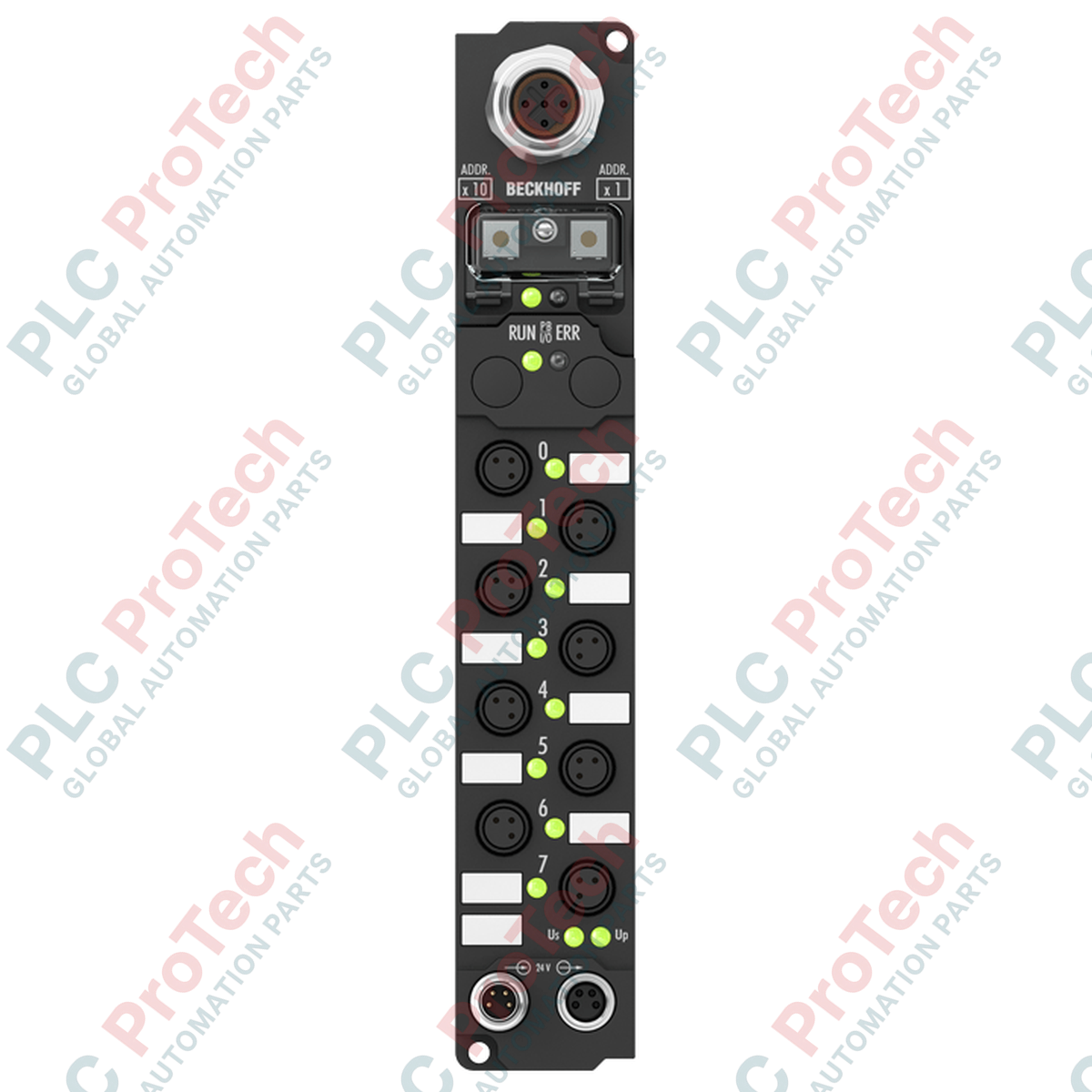
The BECKHOFF IP1010-B528 is a distributed Fieldbus Box designed for digital input acquisition directly within industrial field environments. Equipped with 8 digital input channels, this module captures binary control signals from sensors and transmits them to a centralized automation system. Built to operate on a DeviceNet network, it ensures dependable data exchange in harsh or space-constrained locations.

This compact device features 8 mm snap-type (Ø8) connectors for efficient, tool-free connection of sensor lines. To streamline network topology, the BECKHOFF IP1010-B528 incorporates an integrated M12 T-connector interface. This architecture allows the DeviceNet fieldbus line to be looped directly from one station to the next without requiring external active distribution modules or separate T-pieces.

Engineered for decentralized mounting without a protective control cabinet, the module has a fully sealed polyamide housing. It is designed to withstand mechanical vibrations, high moisture, and dust, making it suitable for distributed machine architectures where direct-to-machine installation is required.

Features

  • 8 digital input channels with a standard 0.2 ms input filter
  • Integrated DeviceNet interface supporting automatic baud rate detection up to 500 kbaud
  • Built-in T-connector using 5-pin M12 connections (one plug, one socket)
  • Space-saving 8 mm snap-type input connection points
  • Protection rating of IP65, IP66, and IP67 for direct environmental exposure
  • Comprehensive local LED diagnostics for channel states and bus status
  • Mechanically stable polyamide construction with integrated mounting holes

Applications

  • Decentralized sensor signal acquisition on automated production lines
  • Material handling systems, sortation systems, and conveyor lines
  • Machine tool and packaging machinery automation assemblies
  • Distributed I/O setups in DeviceNet-controlled plant networks

Technical Specifications

System and Network Data
Fieldbus Protocol DeviceNet
Data Transfer Rates Automatic detection up to 500 kbaud
Bus Interface 1 x M12 plug (5-pin), 1 x M12 socket (5-pin) with integrated T-connector
Process Image Bit Width 8 inputs
Digital Input Parameters
Number of Inputs 8
Input Connection Technology 8 mm snap-type socket (Ø8)
Nominal Input Voltage 24 V DC (-15% / +20%)
Input Filter Time 0.2 ms
"0" Signal Voltage -3 to +5 V (EN 61131-2, type 2)
"1" Signal Voltage 11 to 30 V (EN 61131-2, type 2)
Input Current Typically 6 mA (EN 61131-2, type 2)
Sensor Supply Derived from control voltage, maximum 0.5 A total (short-circuit proof)
Electrical and Auxiliary Data
Control Voltage Supply 24 V DC (-15% / +20%)
Power Supply Connection Feed: 1 x M8 male (4-pin); Downstream: 1 x M8 female (4-pin)
Box Supply Current 45 mA + current consumption of sensors (maximum 0.5 A)
Electrical Isolation Control voltage to fieldbus: 500 V; Channels to control voltage: none
Mechanical and Environmental
Dimensions (W x H x D) 30 mm x 210 mm x 26.5 mm
Housing Material Polyamide (PA6)
Mounting Method 2 x fixing holes (3.5 mm diameter) for M3 screws
Operating Temperature Range 0 to +55 degC
Storage Temperature Range -25 to +85 degC
Protection Rating IP65, IP66, and IP67 (conforming to EN 60529)
Vibration and Shock Resistance Conforms to EN 60068-2-6 and EN 60068-2-27
Approvals and Markings CE, UL

Connections / Interfaces

Interface Type Function and Pin Mapping
DeviceNet Connection (M12) 5-pin plug and socket with integrated T-piece for bus continuation
Digital Inputs (Ø8 mm Sockets) 8 separate snap-in connection points for 24 V DC digital sensors
Power Supply (M8) 4-pin male input feed and 4-pin female downstream feed for power pass-through

Installation Guidelines

  1. Ensure the power supply is completely disconnected and locked out before starting any mechanical installation or wiring.
  2. Mount the module securely using the two integrated 3.5 mm mounting holes and suitable M3 screws, ensuring the mounting surface is flat to avoid stress on the housing.
  3. Connect the DeviceNet communication cables using the built-in M12 plug and socket connections. Tighten the collar nuts to ensure an IP-rated seal.
  4. Wire the 24 V DC control supply to the M8 power feed connector, and daisy-chain to neighboring modules using the downstream M8 socket if required.
  5. Insert the sensor connections into the designated 8 mm snap-type sockets until they engage firmly. Verify that the cable seals are properly seated.
  6. Check local status LEDs upon powering up the system to verify appropriate fieldbus communication and channel states.
Shipping & Returns

Global Express Shipping

  • Standard Delivery: 4–6 business days via DHL, FedEx, and UPS.
  • Express Dispatch: Same-day dispatch for in-stock orders placed before 2:00 PM (GMT+8).
  • Worldwide Coverage: Serving over 150 countries.

Returns & Warranty

  • 30-Day Guarantee: Returns accepted for in-stock products in original, factory-sealed packaging.
  • 12-Month Warranty: Every industrial component is backed by our technical warranty.
Reviews

IP1010-B528

Stock & lead time on request

Call
1 of 1

BECKHOFF IP1010-B528 DeviceNet Fieldbus Box

Only 10 item(s) left in stock
  • Manufacturer: BECKHOFF

  • Product No.: IP1010-B528

  • Country of origin:Germany

  • Product Type: Fieldbus Boxes

  • Payment: T/T, Western Union

  • Weight: 2000g

  • Dimensions: 30 mm x 210 mm x 26.5 mm

  • Shipping port: Xiamen

  • Warranty: 12 months

Quantity
View full details

Product Description

Description

The BECKHOFF IP1010-B528 is a distributed Fieldbus Box designed for digital input acquisition directly within industrial field environments. Equipped with 8 digital input channels, this module captures binary control signals from sensors and transmits them to a centralized automation system. Built to operate on a DeviceNet network, it ensures dependable data exchange in harsh or space-constrained locations.

This compact device features 8 mm snap-type (Ø8) connectors for efficient, tool-free connection of sensor lines. To streamline network topology, the BECKHOFF IP1010-B528 incorporates an integrated M12 T-connector interface. This architecture allows the DeviceNet fieldbus line to be looped directly from one station to the next without requiring external active distribution modules or separate T-pieces.

Engineered for decentralized mounting without a protective control cabinet, the module has a fully sealed polyamide housing. It is designed to withstand mechanical vibrations, high moisture, and dust, making it suitable for distributed machine architectures where direct-to-machine installation is required.

Features

  • 8 digital input channels with a standard 0.2 ms input filter
  • Integrated DeviceNet interface supporting automatic baud rate detection up to 500 kbaud
  • Built-in T-connector using 5-pin M12 connections (one plug, one socket)
  • Space-saving 8 mm snap-type input connection points
  • Protection rating of IP65, IP66, and IP67 for direct environmental exposure
  • Comprehensive local LED diagnostics for channel states and bus status
  • Mechanically stable polyamide construction with integrated mounting holes

Applications

  • Decentralized sensor signal acquisition on automated production lines
  • Material handling systems, sortation systems, and conveyor lines
  • Machine tool and packaging machinery automation assemblies
  • Distributed I/O setups in DeviceNet-controlled plant networks

Technical Specifications

System and Network Data
Fieldbus Protocol DeviceNet
Data Transfer Rates Automatic detection up to 500 kbaud
Bus Interface 1 x M12 plug (5-pin), 1 x M12 socket (5-pin) with integrated T-connector
Process Image Bit Width 8 inputs
Digital Input Parameters
Number of Inputs 8
Input Connection Technology 8 mm snap-type socket (Ø8)
Nominal Input Voltage 24 V DC (-15% / +20%)
Input Filter Time 0.2 ms
"0" Signal Voltage -3 to +5 V (EN 61131-2, type 2)
"1" Signal Voltage 11 to 30 V (EN 61131-2, type 2)
Input Current Typically 6 mA (EN 61131-2, type 2)
Sensor Supply Derived from control voltage, maximum 0.5 A total (short-circuit proof)
Electrical and Auxiliary Data
Control Voltage Supply 24 V DC (-15% / +20%)
Power Supply Connection Feed: 1 x M8 male (4-pin); Downstream: 1 x M8 female (4-pin)
Box Supply Current 45 mA + current consumption of sensors (maximum 0.5 A)
Electrical Isolation Control voltage to fieldbus: 500 V; Channels to control voltage: none
Mechanical and Environmental
Dimensions (W x H x D) 30 mm x 210 mm x 26.5 mm
Housing Material Polyamide (PA6)
Mounting Method 2 x fixing holes (3.5 mm diameter) for M3 screws
Operating Temperature Range 0 to +55 degC
Storage Temperature Range -25 to +85 degC
Protection Rating IP65, IP66, and IP67 (conforming to EN 60529)
Vibration and Shock Resistance Conforms to EN 60068-2-6 and EN 60068-2-27
Approvals and Markings CE, UL

Connections / Interfaces

Interface Type Function and Pin Mapping
DeviceNet Connection (M12) 5-pin plug and socket with integrated T-piece for bus continuation
Digital Inputs (Ø8 mm Sockets) 8 separate snap-in connection points for 24 V DC digital sensors
Power Supply (M8) 4-pin male input feed and 4-pin female downstream feed for power pass-through

Installation Guidelines

  1. Ensure the power supply is completely disconnected and locked out before starting any mechanical installation or wiring.
  2. Mount the module securely using the two integrated 3.5 mm mounting holes and suitable M3 screws, ensuring the mounting surface is flat to avoid stress on the housing.
  3. Connect the DeviceNet communication cables using the built-in M12 plug and socket connections. Tighten the collar nuts to ensure an IP-rated seal.
  4. Wire the 24 V DC control supply to the M8 power feed connector, and daisy-chain to neighboring modules using the downstream M8 socket if required.
  5. Insert the sensor connections into the designated 8 mm snap-type sockets until they engage firmly. Verify that the cable seals are properly seated.
  6. Check local status LEDs upon powering up the system to verify appropriate fieldbus communication and channel states.
Loading product navigation…

Global Express Shipping

  • Standard Delivery: 4-6 Business Days via DHL, FedEx, and UPS.
  • Express Dispatch: Same-day dispatch for in-stock orders placed before 2:00 PM (GMT+8).
  • Worldwide Coverage: Serving over 150 countries, including rapid delivery to Saudi Arabia and UAE.

Returns & Warranty

  • 30-Day Guarantee: Returns accepted for in-stock products in original, factory-sealed packaging.
  • 12-Month Warranty: Every industrial component is backed by our professional technical warranty.

Orders are processed and delivered Monday-Friday (excluding public holidays).


For full eligibility, restocking fees, and international return details, please view our official Refund & Return Policy .

TECHNICAL SPECIFICATIONS

Country of origin
Germany

Technical knowledge

1756-L73 Firmware Upgrade Guide: v19 vs v21/v31 Decision

Replacing a 1756-L73 does not automatically mean upgrading its firmware. This guide compares v19.013, v21.011 and v31.011, focusing on project compatibility, HMI communications, legacy networks and...

Implementing 3-Switch XOR Ladder Logic with Internal Bit

Implement a 3-SPST switch XOR light circuit in LogixPro or RSLogix 500 using an internal relay bit. Includes truth tables, boolean equations, and verified.

Building a Modbus RTU Network with CompactLogix and DeltaV

Integrate Allen-Bradley CompactLogix, Caterpillar ATS, and generators into DeltaV DCS over Modbus RTU. Covers ProSoft MVI69-MCM, Miille DIN266 gateways.

ONS Instruction Not Energizing OTE in Studio 5000 Ladder Logic

ONS instruction fires but the OTE coil never latches in Studio 5000 because the one-shot is only true for one scan. Use OTL/OTU or seal-in logic instead.

Kinetix 5500 EtherNet/IP Network Switch Requirements and Topology

Configure Allen-Bradley Kinetix 5500 servo drives on EtherNet/IP. Covers CIP Sync, IEEE 1588 V2 timing, Stratix selection, DLR topology, and HMI.

Moving Average Filtering in DCS and PLC Analog Control

A moving-average filter is the sliding-window smoother most instrument engineers drop into DCS and PLC analog paths. Here is how the window works, how N and sample time set lag, and when a...