


Replacing ABB DSQC 351: Controller and Network Checks
Checks to record before replacing ABB 3HNE 00006-1 DSQC 351: controller generation, X3/X5/X20/X21 wiring, DeviceNet settings, INTERBUS mapping, and LED states.
Manufacturer: Bently Nevada
Product No.: 3500/32-01-CN
Country of origin:United States
Product Type: Relay Modules
Payment: T/T, Western Union
Weight: 320g
Shipping port: Xiamen
Warranty: 12 months
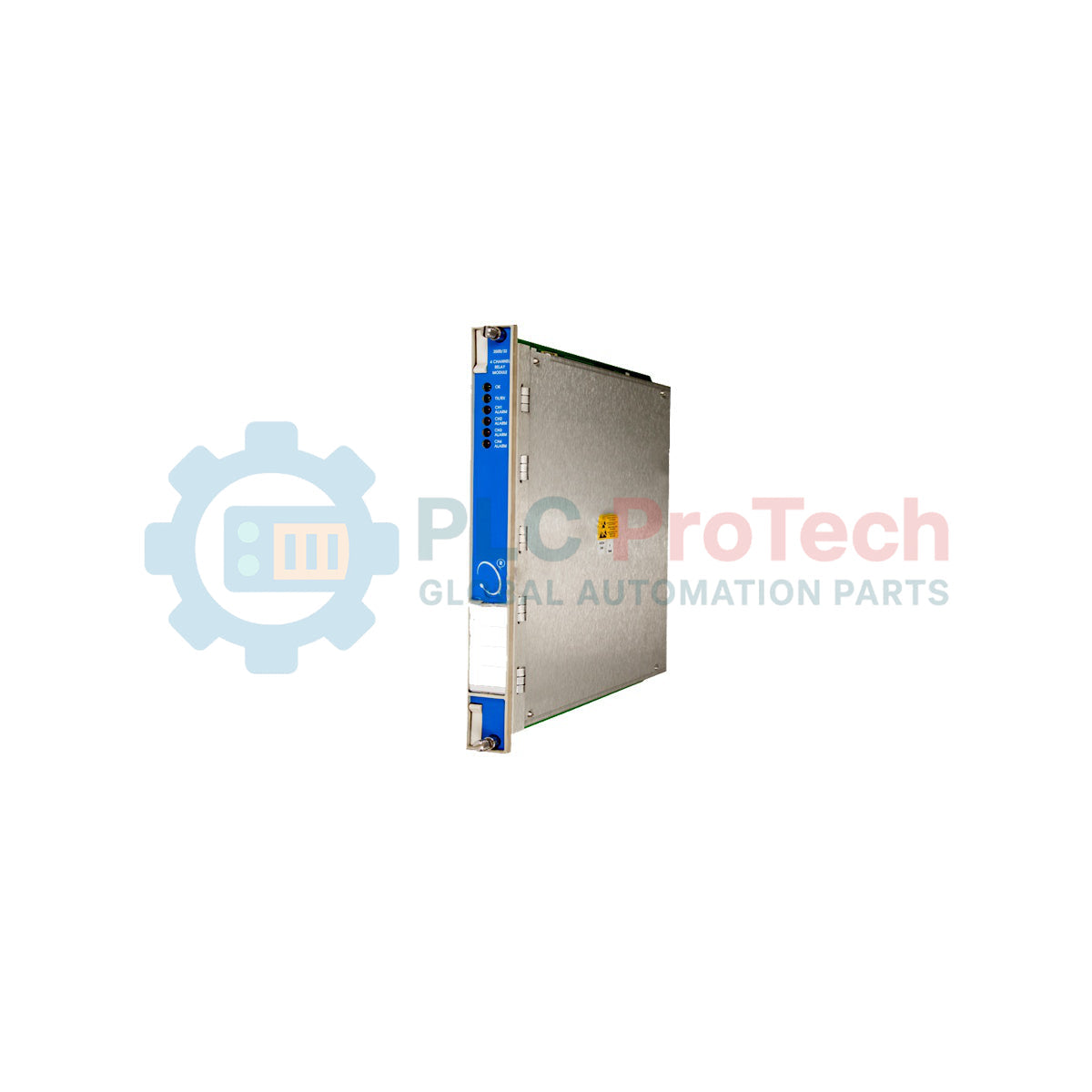
To drive external machinery control loops and execute critical protective safety shutdowns, the Bently Nevada 3500/32-01-CN integrates four fully programmable relay outputs into the 3500 series machinery protection rack. This full-height module accepts input logic from other monitors in the rack to control independent, single-pole double-throw (SPDT) relays. Highly configured for critical safety interlocking, the module provides reliable contact state changes based on alarm status and user-defined voting logic designed in the 3500 Rack Configuration Software.
| Parameter | Value / Specification |
|---|---|
| Manufacturer | Bently Nevada |
| Model Number | 3500/32-01-CN |
| Module Type | 4-Channel Relay Output Module |
| Number of Channels | 4 SPDT Relays |
| Relay Contact Rating (Resistive) | 5 A @ 120 Vac / 240 Vac (Max); 5 A @ 30 Vdc (Max) |
| Minimum Contact Load | 100 mA @ 5 Vdc |
| Agency Approvals Option | CN (Country Specific Approvals) |
| Mounting Location | Any full-height slot except Power Supply and Rack Interface Module slots |
| Country of Origin | USA |
| Shipping Weight (Calculated) | 2.0 kg |
| Terminal Designation | Functional Assignment |
|---|---|
| NO (Normally Open) | Closes connection to Common when relay coil is energized. |
| NC (Normally Closed) | Opens connection to Common when relay coil is energized. |
| COM (Common) | Common reference pole for the respective channel's SPDT contact circuit. |
While the 3500 system also supports a 16-Channel Relay Module (the 3500/33), the 4-Channel 3500/32 provides robust SPDT Form-C outputs which are typically preferred for direct trip solenoid activation. Ensure that the 3500/32 firmware revision is compatible with your Rack Interface Module (RIM) firmware version before attempting slot allocation changes.
When switching highly inductive AC loads (such as heavy solenoid valves or larger motor starters), installing external arc-suppression (RC snubbers) across the contacts is critical to prevent contact erosion and premature welding. Operating close to the 5 A limit without suppression can degrade relay lifespans and lead to dangerous "fail-to-open" states.
Always configure the "OK Relay" function correctly inside the configuration panel. Under normal running conditions, we recommend operating safety shutdown loops in a Normally Energized (NE) de-energize-to-trip mode. This ensures that a total loss of instrument control power automatically triggers the safe state of the machinery loop.
Power down the 3500 rack system if hot-swapping is not permitted by plant safety procedures. (The 3500 system supports hot-swapping under specific restricted environmental conditions).
Insert the main 3500/32-01-CN module into the front of the rack, sliding it along the guide rails until it is firmly seated in the backplane connector. Tighten the two securing screws on the front panel.
Mount the corresponding 4-channel relay I/O module into the back of the rack directly behind the front-facing slot. Secure it with its chassis panel screws.
Connect your alarm loop field wiring to the rear terminal block using proper wire-end ferrules to guarantee mechanical integrity and prevent short-circuiting between adjacent contact terminals.

Global Express Shipping
Returns & Warranty


Global Express Shipping
Returns & Warranty
Orders are processed and delivered Monday-Friday (excluding public holidays).
For full eligibility, restocking fees, and international return details, please view our official Refund & Return Policy .
| Country of origin |
United States
|

Checks to record before replacing ABB 3HNE 00006-1 DSQC 351: controller generation, X3/X5/X20/X21 wiring, DeviceNet settings, INTERBUS mapping, and LED states.

Compare the IC693CPU360 and IC693CPU364 by Ethernet interface, +5 VDC load, memory, rack limits, and replacement checks.

A field-first diagnostic sequence for 1756-OF4 analog output problems: channel mode, removable terminal block, scaling, and controlled electrical checks.

A direct comparison of 1746-OA8 and 1746-OA16 output count, common grouping, backplane current and temperature-derated load limits.

A field checklist for recording the 1761-NET-DNI hardware series, firmware, EDS file, DF1 settings, DeviceNet address and messaging configuration before replacement.

The EL3062 is a 0–10 V EtherCAT terminal. The EL3062-0030 is a 0–30 V variant. This checklist covers identification, scaling and commissioning.