Honeywell

Honeywell 10102/2/1 11301 FSC Fail-Safe Analog Input Module

SKU 10102/2/1

In stock
  • 12-month warranty
  • Free returns within 30 days
  • Manufacturer: Honeywell
  • Product No.: 10102/2/1
  • Origin United States
  • Product Type: Analog Input Modules
  • Payment: T/T, Western Union
  • Weight: 0.45 kg
  • Dimensions: 20 x 130 x 260 mm
  • Shipping port: Xiamen
  • Warranty: 12 months

Tags

Product Documentation

Technical Datasheet (PDF) Complete specifications and technical drawings.

Technical Datasheet

Honeywell 10102/2/1 11301 FSC Fail-Safe Analog Input Module

Quantity

Product Description

Description

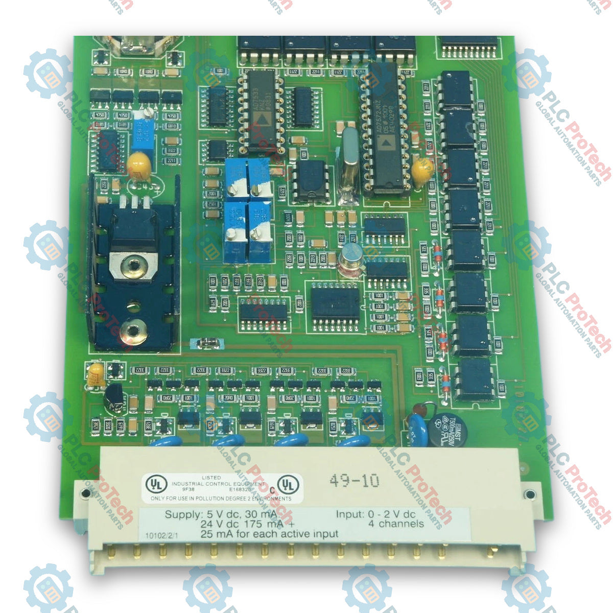
The Honeywell 10102/2/1 is a 4-channel fail-safe analog input module designed for safety-critical application in Honeywell Fail Safe Control (FSC) systems. Featuring a native 0-2 Vdc input range, the inputs share a common 0 V connection and are galvanically isolated from the internal 24 Vdc and 5 Vdc supply rails.

The module supports both active mode (supplying individual 26 Vdc short-circuit protected loop power for field transmitters) and passive mode (utilizing external transmitter power). Due to its high input impedance, two 10102/2/1 modules can be wired in parallel for enhanced redundancy. Every input channel requires an external analog input converter module (10102/A/x series), making this module strictly compatible with I/O backplanes in the FSC rack.

Integrated self-diagnostics continuously monitor process safety times by testing absolute accuracy, full-range conversion integrity, inter-channel crosstalk, and internal reference voltages generated via an onboard D/A converter.

Features

  • 4 Galvanically Isolated Input Channels: Standard 0-2 Vdc direct input range, isolated from internal 5 Vdc and 24 Vdc electronics.
  • Active/Passive Power Support: Provides active 26 Vdc power output for loop-powered transmitters, or accepts passive input signals from externally powered devices.
  • Parallel Capability: High input impedance allows parallel wiring of two 10102/2/1 modules to double system signal distribution.
  • Comprehensive Self-Testing: Scans inputs, internal supplies, and 26 Vdc outputs within configured process safety time windows, including input filter leakage testing.
  • EMC Enhanced Variant: Module suffix 11301 features upgraded electromagnetic compatibility (EMC) protection.
  • 12-Bit Resolution A/D Conversion: High-accuracy digital conversion with <= 0.75% total inaccuracy.

Technical Specifications

General & Power Requirements

Parameter Specification
Manufacturer Honeywell Safety Management Systems
Type Number 10102/2/1 (11301* with enhanced EMC behavior)
Approvals CE, TÜV, UL
Software Compatibility >= 3.00
Space Requirements 4 TE, 3 HE (= 4 HP, 3U)
Power Consumption (5 Vdc) 30 mA
Power Consumption (24 Vdc) 175 mA + 25 mA per active input channel

Input Performance

Parameter Specification
Channels 4
Input Range 0-2 Vdc
Input Resistance > 100 kOhm
Absolute Max. Input Signal +/- 5 Vdc
A/D Converter 12-bit
Inaccuracy <= 0.75%
Loop Powering 26 Vdc (+/- 1 V for 0.2 mA < I < 20 mA), short-circuit protected
Loop Current Limit > 21 mA (solid state)

Mechanical Key Coding

Connector Type Code Pin Locations
Module Connector Holes A5, C17
Rack Connector Large Pins A5, C17

FSC Analog Input Signal Matching (10102/A/x Compatibility)

To interface standard field instrumentation, the 10102/2/1 must be paired with the appropriate 10102/A/x converter module as detailed below:

Field Signal Range Power Source Module Combination
0(4)-20 mA Internal power (Active) 10102/2/1 + 10102/A/1
0(4)-20 mA External power (Passive) 10102/2/1 + 10102/A/2
0(1)-5 V External power 10102/2/1 + 10102/A/3
0(2)-10 V External power 10102/2/1 + 10102/A/4
Loop-monitored Digital Input Direct / Field Power 10102/2/1 + 10102/A/5

Note: Non-standard signals (e.g., Thermocouples, PT-100 RTDs) must be pre-converted into standard voltage or current loops prior to connecting to the 10102/A/x adapters.

Installation Guidelines

  1. Pre-Installation Safety Inspection: Verify the physical integrity of the Eurocard housing, backplane pin connectors, and key-coding mechanism. Ensure system power down or follow plant-specific hot-swap safety protocols before inserting the module into an active rack.
  2. Mechanical Keying Alignment: Confirm the backplane slot is key-coded to match the module's key pattern (A5 C17 for model 10102/2/1). Do not force the card if resistance is met, as bent keying pins must be replaced rather than re-bent.
  3. Rack Insertion: Carefully align the module card edges with the top and bottom guide rails of the designated FSC I/O rack. Slide the module firmly into place until the rear backplane connectors seat completely. Tighten front panel retaining screws to secure grounding and mechanical engagement.
  4. Field Wiring and Converter Module Setup: Verify signal conditioning wiring via the appropriate Field Termination Assembly (FTA) or external resistor conversion network (e.g., converting 4-20 mA or 0-10 V inputs into the required module voltage level). Ensure shielded twisted-pair cabling is grounded at one end to prevent ground loop interference.

Configuration and Commissioning

  1. System Software Configuration: Open the FSC user station software and assign the module to its precise rack and slot position as defined in the project hardware layout. Confirm software revision compatibility is set to version 3.00 or higher.
  2. Signal Calibration and Loop Verification: Inject calibrated reference signals (e.g., 4 mA, 12 mA, and 20 mA via a loop calibrator) at the FTA terminals. Check the software engineering units and diagnostic display to confirm analog-to-digital conversion accuracy across all 4 channels.
  3. Diagnostic Verification: Monitor front panel status LEDs and the Diagnostic and Battery Module (DBM) system status to ensure no channel fault, open-loop condition, or backplane communication error is reported.

Compliance and Certifications

  • DIN V 19250 / DIN V 0801: Certified for safety-critical applications up to Requirement Class AK 8.
  • CE Compliance: Conforms to European EMC Directive (89/336/EEC) and Low Voltage Directive (73/23/EEC).
  • Industrial Safety Standards: Complies with EN 61131-2 (Programmable Controllers) and UL 508 / UL 1998 (Safety-Related Software and Control Equipment).
  • Environmental Testing: Tested to DIN IEC 68 Part 2 standards for cold, dry heat, damp heat, shock, and sinusoidal vibration.
Shipping &amp; Returns

Global Express Shipping

  • Standard Delivery: 4–6 business days via DHL, FedEx, and UPS.
  • Express Dispatch: Same-day dispatch for in-stock orders placed before 2:00 PM (GMT+8).
  • Worldwide Coverage: Serving over 150 countries.

Returns & Warranty

  • 30-Day Guarantee: Returns accepted for in-stock products in original, factory-sealed packaging.
  • 12-Month Warranty: Every industrial component is backed by our technical warranty.
FAQ
What is the primary function of the Honeywell 10102/2/1 module in an FSC system?
The module serves as a 4-channel fail-safe analog input interface within Honeywell Fail Safe Control systems. It processes analog field signals from instruments like transmitters and sensors, converting them into digital data for safety logic execution in ESD and fire and gas applications.
How does the key-coding system protect the Honeywell 10102/2/1 during installation?
As a plug-and-play module (type 10xxx/2/x), it uses specific Souriau mechanical coding pin positions (A5 C17). This prevents the module from being accidentally inserted into an incorrect rack slot, protecting field wiring and system components from voltage mismatches.
What software version is required to operate the Honeywell 10102/2/1 module?
The module requires FSC system software version 3.00 or higher. System engineers must verify software compatibility in the FSC user station configuration tool prior to module commissioning.
How are field current signals like 4-20 mA connected to the 10102/2/1 input channels?
Direct module inputs accept 0-2 Vdc signals. To interface standard 0(4)-20 mA or higher voltage field loops, external analog input converter modules or Field Termination Assemblies (FTAs) are used to scale field signals to the module's native input range.
Reviews

10102/2/1

Stock &amp; lead time on request

Call
1 of 4

Honeywell 10102/2/1 11301 FSC Fail-Safe Analog Input Module

Only 3 item(s) left in stock
  • Manufacturer: Honeywell

  • Product No.: 10102/2/1

  • Country of origin:United States

  • Product Type: Analog Input Modules

  • Payment: T/T, Western Union

  • Weight: 450g

  • Dimensions: 20 x 130 x 260 mm

  • Shipping port: Xiamen

  • Warranty: 12 months

Quantity
View full details

Description

The Honeywell 10102/2/1 is a 4-channel fail-safe analog input module designed for safety-critical application in Honeywell Fail Safe Control (FSC) systems. Featuring a native 0-2 Vdc input range, the inputs share a common 0 V connection and are galvanically isolated from the internal 24 Vdc and 5 Vdc supply rails.

The module supports both active mode (supplying individual 26 Vdc short-circuit protected loop power for field transmitters) and passive mode (utilizing external transmitter power). Due to its high input impedance, two 10102/2/1 modules can be wired in parallel for enhanced redundancy. Every input channel requires an external analog input converter module (10102/A/x series), making this module strictly compatible with I/O backplanes in the FSC rack.

Integrated self-diagnostics continuously monitor process safety times by testing absolute accuracy, full-range conversion integrity, inter-channel crosstalk, and internal reference voltages generated via an onboard D/A converter.

Features

  • 4 Galvanically Isolated Input Channels: Standard 0-2 Vdc direct input range, isolated from internal 5 Vdc and 24 Vdc electronics.
  • Active/Passive Power Support: Provides active 26 Vdc power output for loop-powered transmitters, or accepts passive input signals from externally powered devices.
  • Parallel Capability: High input impedance allows parallel wiring of two 10102/2/1 modules to double system signal distribution.
  • Comprehensive Self-Testing: Scans inputs, internal supplies, and 26 Vdc outputs within configured process safety time windows, including input filter leakage testing.
  • EMC Enhanced Variant: Module suffix 11301 features upgraded electromagnetic compatibility (EMC) protection.
  • 12-Bit Resolution A/D Conversion: High-accuracy digital conversion with <= 0.75% total inaccuracy.

Technical Specifications

General & Power Requirements

Parameter Specification
Manufacturer Honeywell Safety Management Systems
Type Number 10102/2/1 (11301* with enhanced EMC behavior)
Approvals CE, TÜV, UL
Software Compatibility >= 3.00
Space Requirements 4 TE, 3 HE (= 4 HP, 3U)
Power Consumption (5 Vdc) 30 mA
Power Consumption (24 Vdc) 175 mA + 25 mA per active input channel

Input Performance

Parameter Specification
Channels 4
Input Range 0-2 Vdc
Input Resistance > 100 kOhm
Absolute Max. Input Signal +/- 5 Vdc
A/D Converter 12-bit
Inaccuracy <= 0.75%
Loop Powering 26 Vdc (+/- 1 V for 0.2 mA < I < 20 mA), short-circuit protected
Loop Current Limit > 21 mA (solid state)

Mechanical Key Coding

Connector Type Code Pin Locations
Module Connector Holes A5, C17
Rack Connector Large Pins A5, C17

FSC Analog Input Signal Matching (10102/A/x Compatibility)

To interface standard field instrumentation, the 10102/2/1 must be paired with the appropriate 10102/A/x converter module as detailed below:

Field Signal Range Power Source Module Combination
0(4)-20 mA Internal power (Active) 10102/2/1 + 10102/A/1
0(4)-20 mA External power (Passive) 10102/2/1 + 10102/A/2
0(1)-5 V External power 10102/2/1 + 10102/A/3
0(2)-10 V External power 10102/2/1 + 10102/A/4
Loop-monitored Digital Input Direct / Field Power 10102/2/1 + 10102/A/5

Note: Non-standard signals (e.g., Thermocouples, PT-100 RTDs) must be pre-converted into standard voltage or current loops prior to connecting to the 10102/A/x adapters.

Installation Guidelines

  1. Pre-Installation Safety Inspection: Verify the physical integrity of the Eurocard housing, backplane pin connectors, and key-coding mechanism. Ensure system power down or follow plant-specific hot-swap safety protocols before inserting the module into an active rack.
  2. Mechanical Keying Alignment: Confirm the backplane slot is key-coded to match the module's key pattern (A5 C17 for model 10102/2/1). Do not force the card if resistance is met, as bent keying pins must be replaced rather than re-bent.
  3. Rack Insertion: Carefully align the module card edges with the top and bottom guide rails of the designated FSC I/O rack. Slide the module firmly into place until the rear backplane connectors seat completely. Tighten front panel retaining screws to secure grounding and mechanical engagement.
  4. Field Wiring and Converter Module Setup: Verify signal conditioning wiring via the appropriate Field Termination Assembly (FTA) or external resistor conversion network (e.g., converting 4-20 mA or 0-10 V inputs into the required module voltage level). Ensure shielded twisted-pair cabling is grounded at one end to prevent ground loop interference.

Configuration and Commissioning

  1. System Software Configuration: Open the FSC user station software and assign the module to its precise rack and slot position as defined in the project hardware layout. Confirm software revision compatibility is set to version 3.00 or higher.
  2. Signal Calibration and Loop Verification: Inject calibrated reference signals (e.g., 4 mA, 12 mA, and 20 mA via a loop calibrator) at the FTA terminals. Check the software engineering units and diagnostic display to confirm analog-to-digital conversion accuracy across all 4 channels.
  3. Diagnostic Verification: Monitor front panel status LEDs and the Diagnostic and Battery Module (DBM) system status to ensure no channel fault, open-loop condition, or backplane communication error is reported.

Compliance and Certifications

  • DIN V 19250 / DIN V 0801: Certified for safety-critical applications up to Requirement Class AK 8.
  • CE Compliance: Conforms to European EMC Directive (89/336/EEC) and Low Voltage Directive (73/23/EEC).
  • Industrial Safety Standards: Complies with EN 61131-2 (Programmable Controllers) and UL 508 / UL 1998 (Safety-Related Software and Control Equipment).
  • Environmental Testing: Tested to DIN IEC 68 Part 2 standards for cold, dry heat, damp heat, shock, and sinusoidal vibration.
Loading product navigation…

Product Documentation

Technical Datasheet (PDF) Complete specifications and technical drawings.

Technical Datasheet

Honeywell 10102/2/1 11301 FSC Fail-Safe Analog Input Module

What is the primary function of the Honeywell 10102/2/1 module in an FSC system?

The module serves as a 4-channel fail-safe analog input interface within Honeywell Fail Safe Control systems. It processes analog field signals from instruments like transmitters and sensors, converting them into digital data for safety logic execution in ESD and fire and gas applications.

How does the key-coding system protect the Honeywell 10102/2/1 during installation?

As a plug-and-play module (type 10xxx/2/x), it uses specific Souriau mechanical coding pin positions (A5 C17). This prevents the module from being accidentally inserted into an incorrect rack slot, protecting field wiring and system components from voltage mismatches.

What software version is required to operate the Honeywell 10102/2/1 module?

The module requires FSC system software version 3.00 or higher. System engineers must verify software compatibility in the FSC user station configuration tool prior to module commissioning.

How are field current signals like 4-20 mA connected to the 10102/2/1 input channels?

Direct module inputs accept 0-2 Vdc signals. To interface standard 0(4)-20 mA or higher voltage field loops, external analog input converter modules or Field Termination Assemblies (FTAs) are used to scale field signals to the module's native input range.

Global Express Shipping

  • Standard Delivery: 4-6 Business Days via DHL, FedEx, and UPS.
  • Express Dispatch: Same-day dispatch for in-stock orders placed before 2:00 PM (GMT+8).
  • Worldwide Coverage: Serving over 150 countries, including rapid delivery to Saudi Arabia and UAE.

Returns & Warranty

  • 30-Day Guarantee: Returns accepted for in-stock products in original, factory-sealed packaging.
  • 12-Month Warranty: Every industrial component is backed by our professional technical warranty.

Orders are processed and delivered Monday-Friday (excluding public holidays).


For full eligibility, restocking fees, and international return details, please view our official Refund & Return Policy .

TECHNICAL SPECIFICATIONS

Color pattern
Green
Country of origin
United States
Power source
DC Power

Recently Viewed Products

Technical knowledge

Implementing 3-Switch XOR Ladder Logic with Internal Bit

Implement a 3-SPST switch XOR light circuit in LogixPro or RSLogix 500 using an internal relay bit. Includes truth tables, boolean equations, and verified.

Building a Modbus RTU Network with CompactLogix and DeltaV

Integrate Allen-Bradley CompactLogix, Caterpillar ATS, and generators into DeltaV DCS over Modbus RTU. Covers ProSoft MVI69-MCM, Miille DIN266 gateways.

ONS Instruction Not Energizing OTE in Studio 5000 Ladder Logic

ONS instruction fires but the OTE coil never latches in Studio 5000 because the one-shot is only true for one scan. Use OTL/OTU or seal-in logic instead.

Kinetix 5500 EtherNet/IP Network Switch Requirements and Topology

Configure Allen-Bradley Kinetix 5500 servo drives on EtherNet/IP. Covers CIP Sync, IEEE 1588 V2 timing, Stratix selection, DLR topology, and HMI.

Moving Average Filtering in DCS and PLC Analog Control

A moving-average filter is the sliding-window smoother most instrument engineers drop into DCS and PLC analog paths. Here is how the window works, how N and sample time set lag, and when a...

GE Mark VI Function Blocks for Gas Turbine Control Logic

On Frame 5–9 gas turbines, GE Mark VI and Mark VIe run control as function-block application software. This article maps process, protection, and sequencing functions—and what Toolbox ST access...