Honeywell

Honeywell FS-PSU-UNI2450U Safety Manager 24–28 V DC 50 A 1200 W Power Supply Module

SKU FS-PSU-UNI2450U

In stock
  • 12-month warranty
  • Free returns within 30 days
  • Manufacturer: Honeywell
  • Product No.: FS-PSU-UNI2450U
  • Origin United States
  • Product Type: Power Supply Modules
  • Payment: T/T, Western Union
  • Weight: 3.5 kg
  • Dimensions: 130 x 185 x 295 mm
  • Shipping port: Xiamen
  • Warranty: 12 months

Tags

Product Documentation

Technical Datasheet (PDF) Complete specifications and technical drawings.

Technical Datasheet

Honeywell FS-PSU-UNI2450U Safety Manager 24–28 V DC 50 A 1200 W Power Supply Module

Quantity

Product Description

Description

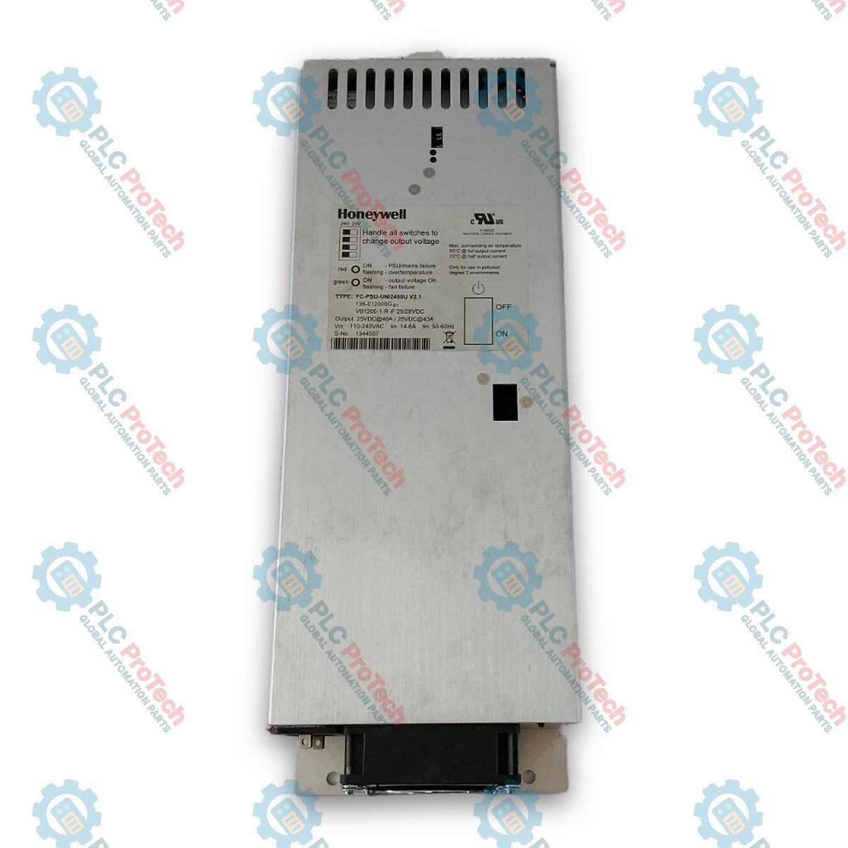
The Honeywell FS-PSU-UNI2450U is a high-capacity switch-mode power supply module designed for use within Honeywell Safety Manager architecture and industrial control systems. Operating as a core power conversion element, it converts single-phase AC or DC mains voltage into a regulated 24–28 V DC output to supply field devices, Control Processor chassis, and I/O modules in critical safety instrumented systems (SIS).

Engineered to deliver up to 1200 W output power, the FS-PSU-UNI2450U features active Power Factor Correction (PFC), short-circuit and overvoltage protection, and a built-in alarm relay contact for continuous status monitoring. The module supports flexible system topologies and can be deployed in non-redundant (N), redundant (N+1), or fully redundant (Nx2) power supply configurations to ensure maximum operational uptime.

The front panel includes a mechanical power switch, a four-position output voltage selector switch, status LEDs, and test points for output voltage verification. Designed for cabinet or carrier mounting in industrial automation environments, the unit incorporates active fan cooling to maintain stable continuous operation across demanding load profiles.

Features

  • High-Power Capacity: Delivers continuous output power up to 1200 W with a maximum current rating of 50 A at 24 V DC.
  • Selectable Output Voltage: Four-position rotary selector switch provides adjustable output settings for 25.0 V, 26.0 V, 27.0 V, and 28.0 V DC.
  • Wide Input Voltage Range: Accepts 100–240 V AC nominal (85–265 V AC limits) and 110–250 V DC input sources.
  • Active Power Factor Correction: Built-in active PFC ensures high energy efficiency with a power factor exceeding 0.95 at 230 V AC full load.
  • Integrated Alarm Monitoring: Dry contact alarm relay triggers on low output voltage (<22 V DC) or overtemperature conditions.
  • Redundancy Support: Compatible with N, N+1, and Nx2 redundant power supply and feeder topologies in Safety Manager systems.
  • Protective Features: Includes electronic short-circuit protection, overvoltage shutdown, and thermal protection with auto-recovery.

Applications

  • Main 24 V DC system power supply for Honeywell Safety Manager cabinets.
  • Power source for Control Processor chassis, I/O chassis, and Field Termination Assemblies (FTAs).
  • Power distribution in Safety Instrumented Systems (SIS), Emergency Shutdown (ESD) systems, and Fire and Gas (F&G) protection architecture.
  • Redundant field instrument and output loop power supply.

Technical Specifications

General

Parameter Specification
Manufacturer Honeywell
Part Number FS-PSU-UNI2450U
Model Reference PSU-UNI2450U
Product Type Power Supply Module
Weight 3.5 kg

Input Electrical Ratings

Parameter Specification
Nominal Input Voltage Range (AC) 100–240 V AC
Input Voltage Limits (AC) 85–265 V AC
Nominal Input Frequency 50 / 60 Hz
Input Frequency Limits 45–65 Hz
Input Voltage Range (DC) 110–250 V DC
Maximum Input Current 15 A at 100 V AC / 6 A at 230 V AC
Inrush Current < 30 A (cold start at 230 V AC)
Power Factor > 0.95 at 230 V AC (full load)
Efficiency > 85% at full load

Output Electrical Ratings

Parameter Specification
Output Voltage Range 24–28 V DC
Voltage Switch Settings 25.0 V DC, 26.0 V DC, 27.0 V DC, 28.0 V DC
Nominal Output Current 50 A (at 24 V DC)
Maximum Continuous Power 1200 W
Line Regulation < 0.2%
Load Regulation < 0.5%
Ripple and Noise < 100 mV peak-to-peak
Hold-up Time > 20 ms at nominal AC input and full load

Protection and Diagnostics

Parameter Specification
Short Circuit Protection Electronic current limiting with automatic recovery
Overvoltage Protection Shutdown above nominal setpoint (approx. 32 V DC limit)
Overtemperature Protection Internal thermal shutdown with automatic recovery
Alarm Contact Type Potential-free changeover relay contact
Alarm Contact Rating 30 V DC / 1 A, 125 V AC / 0.5 A
Alarm Threshold Low output voltage (< 22 V DC) or internal thermal fault

Environmental and Cooling

Parameter Specification
Operating Temperature 0 to +70 degC (derating applies above 50 degC)
Storage Temperature -40 to +85 degC
Relative Humidity 5% to 95% non-condensing
Cooling Method Internal forced air (integrated cooling fans)

Connections / Interfaces

Interface / Connector Function
AC/DC Input Terminals Screw terminals for Line (L), Neutral (N), and Protective Earth (PE)
DC Output Terminals High-current screw terminals for positive (+24V to +28V DC) and negative (0V) connections
Alarm Contact Terminals Screw terminals for potential-free relay status readback (NO/NC/COM)
Output Voltage Selector Switch 4-position rotary selector switch for setting 25V, 26V, 27V, or 28V DC output voltage
Voltage Test Points Front panel test sockets for DC multimeter output voltage measurement

Installation Guidelines

  1. Safety Pre-Installation Verification: Confirm that incoming mains power supply matches the rated input specifications (85–265 V AC or 110–250 V DC) and that the main breaker is locked out before installation.
  2. Mounting: Securely mount the module within the designated Safety Manager cabinet or power rack. Ensure unobstructed airflow at both top and bottom ventilation openings to maintain optimal fan cooling.
  3. Protective Earth Grounding: Wire the Protective Earth (PE) terminal directly to the cabinet ground bus prior to making any power connections.
  4. Input and Output Wiring: Connect incoming AC or DC supply cables to the input terminal block using recommended wire gauges capable of handling up to 15 A continuous current. Connect the DC output terminals to the main power rail or feeder unit using high-current conductors.
  5. Voltage Selection: Adjust the 4-position rotary selector switch to the desired system voltage level (25 V, 26 V, 27 V, or 28 V DC) before energizing the system.
  6. Alarm Contact Integration: Wire the potential-free alarm contact to the system monitoring channel or watchdog board to capture fault signals such as output undervoltage or overtemperature.
  7. Commissioning Inspection: Measure output voltage across front-panel test sockets using a calibrated digital multimeter before applying power to downstream processors or I/O modules.
Shipping &amp; Returns

Global Express Shipping

  • Standard Delivery: 4–6 business days via DHL, FedEx, and UPS.
  • Express Dispatch: Same-day dispatch for in-stock orders placed before 2:00 PM (GMT+8).
  • Worldwide Coverage: Serving over 150 countries.

Returns & Warranty

  • 30-Day Guarantee: Returns accepted for in-stock products in original, factory-sealed packaging.
  • 12-Month Warranty: Every industrial component is backed by our technical warranty.
FAQ
What is the primary function of the Honeywell FS-PSU-UNI2450U?
The FS-PSU-UNI2450U is a high-capacity 1200 W switch-mode power supply module designed to convert AC or DC mains voltage into a regulated 24–28 V DC output. It powers Control Processor chassis, I/O modules, and field devices within Honeywell Safety Manager systems.
What output voltage settings are selectable on the FS-PSU-UNI2450U?
The module includes a four-position rotary switch on the front panel that allows technicians to set the output voltage to 25.0 V, 26.0 V, 27.0 V, or 28.0 V DC depending on system wiring lengths and voltage drop requirements.
Can the FS-PSU-UNI2450U be used in redundant power configurations?
Yes, the module is designed for non-redundant (N), redundant (N+1), and fully redundant (Nx2) power supply and feeder configurations in Honeywell Safety Manager control cabinets.
How does the FS-PSU-UNI2450U indicate fault conditions?
The unit features front-panel status LEDs and a built-in potential-free alarm relay contact. The alarm contact opens or closes to signal system diagnostics if the output voltage drops below 22 V DC or if internal overtemperature is detected.
Reviews

FS-PSU-UNI2450U

Stock &amp; lead time on request

Call
1 of 7

Honeywell FS-PSU-UNI2450U Safety Manager 24–28 V DC 50 A 1200 W Power Supply Module

Only 8 item(s) left in stock
  • Manufacturer: Honeywell

  • Product No.: FS-PSU-UNI2450U

  • Country of origin:United States

  • Product Type: Power Supply Modules

  • Payment: T/T, Western Union

  • Weight: 3500g

  • Dimensions: 130 x 185 x 295 mm

  • Shipping port: Xiamen

  • Warranty: 12 months

Quantity
View full details

Description

The Honeywell FS-PSU-UNI2450U is a high-capacity switch-mode power supply module designed for use within Honeywell Safety Manager architecture and industrial control systems. Operating as a core power conversion element, it converts single-phase AC or DC mains voltage into a regulated 24–28 V DC output to supply field devices, Control Processor chassis, and I/O modules in critical safety instrumented systems (SIS).

Engineered to deliver up to 1200 W output power, the FS-PSU-UNI2450U features active Power Factor Correction (PFC), short-circuit and overvoltage protection, and a built-in alarm relay contact for continuous status monitoring. The module supports flexible system topologies and can be deployed in non-redundant (N), redundant (N+1), or fully redundant (Nx2) power supply configurations to ensure maximum operational uptime.

The front panel includes a mechanical power switch, a four-position output voltage selector switch, status LEDs, and test points for output voltage verification. Designed for cabinet or carrier mounting in industrial automation environments, the unit incorporates active fan cooling to maintain stable continuous operation across demanding load profiles.

Features

  • High-Power Capacity: Delivers continuous output power up to 1200 W with a maximum current rating of 50 A at 24 V DC.
  • Selectable Output Voltage: Four-position rotary selector switch provides adjustable output settings for 25.0 V, 26.0 V, 27.0 V, and 28.0 V DC.
  • Wide Input Voltage Range: Accepts 100–240 V AC nominal (85–265 V AC limits) and 110–250 V DC input sources.
  • Active Power Factor Correction: Built-in active PFC ensures high energy efficiency with a power factor exceeding 0.95 at 230 V AC full load.
  • Integrated Alarm Monitoring: Dry contact alarm relay triggers on low output voltage (<22 V DC) or overtemperature conditions.
  • Redundancy Support: Compatible with N, N+1, and Nx2 redundant power supply and feeder topologies in Safety Manager systems.
  • Protective Features: Includes electronic short-circuit protection, overvoltage shutdown, and thermal protection with auto-recovery.

Applications

  • Main 24 V DC system power supply for Honeywell Safety Manager cabinets.
  • Power source for Control Processor chassis, I/O chassis, and Field Termination Assemblies (FTAs).
  • Power distribution in Safety Instrumented Systems (SIS), Emergency Shutdown (ESD) systems, and Fire and Gas (F&G) protection architecture.
  • Redundant field instrument and output loop power supply.

Technical Specifications

General

Parameter Specification
Manufacturer Honeywell
Part Number FS-PSU-UNI2450U
Model Reference PSU-UNI2450U
Product Type Power Supply Module
Weight 3.5 kg

Input Electrical Ratings

Parameter Specification
Nominal Input Voltage Range (AC) 100–240 V AC
Input Voltage Limits (AC) 85–265 V AC
Nominal Input Frequency 50 / 60 Hz
Input Frequency Limits 45–65 Hz
Input Voltage Range (DC) 110–250 V DC
Maximum Input Current 15 A at 100 V AC / 6 A at 230 V AC
Inrush Current < 30 A (cold start at 230 V AC)
Power Factor > 0.95 at 230 V AC (full load)
Efficiency > 85% at full load

Output Electrical Ratings

Parameter Specification
Output Voltage Range 24–28 V DC
Voltage Switch Settings 25.0 V DC, 26.0 V DC, 27.0 V DC, 28.0 V DC
Nominal Output Current 50 A (at 24 V DC)
Maximum Continuous Power 1200 W
Line Regulation < 0.2%
Load Regulation < 0.5%
Ripple and Noise < 100 mV peak-to-peak
Hold-up Time > 20 ms at nominal AC input and full load

Protection and Diagnostics

Parameter Specification
Short Circuit Protection Electronic current limiting with automatic recovery
Overvoltage Protection Shutdown above nominal setpoint (approx. 32 V DC limit)
Overtemperature Protection Internal thermal shutdown with automatic recovery
Alarm Contact Type Potential-free changeover relay contact
Alarm Contact Rating 30 V DC / 1 A, 125 V AC / 0.5 A
Alarm Threshold Low output voltage (< 22 V DC) or internal thermal fault

Environmental and Cooling

Parameter Specification
Operating Temperature 0 to +70 degC (derating applies above 50 degC)
Storage Temperature -40 to +85 degC
Relative Humidity 5% to 95% non-condensing
Cooling Method Internal forced air (integrated cooling fans)

Connections / Interfaces

Interface / Connector Function
AC/DC Input Terminals Screw terminals for Line (L), Neutral (N), and Protective Earth (PE)
DC Output Terminals High-current screw terminals for positive (+24V to +28V DC) and negative (0V) connections
Alarm Contact Terminals Screw terminals for potential-free relay status readback (NO/NC/COM)
Output Voltage Selector Switch 4-position rotary selector switch for setting 25V, 26V, 27V, or 28V DC output voltage
Voltage Test Points Front panel test sockets for DC multimeter output voltage measurement

Installation Guidelines

  1. Safety Pre-Installation Verification: Confirm that incoming mains power supply matches the rated input specifications (85–265 V AC or 110–250 V DC) and that the main breaker is locked out before installation.
  2. Mounting: Securely mount the module within the designated Safety Manager cabinet or power rack. Ensure unobstructed airflow at both top and bottom ventilation openings to maintain optimal fan cooling.
  3. Protective Earth Grounding: Wire the Protective Earth (PE) terminal directly to the cabinet ground bus prior to making any power connections.
  4. Input and Output Wiring: Connect incoming AC or DC supply cables to the input terminal block using recommended wire gauges capable of handling up to 15 A continuous current. Connect the DC output terminals to the main power rail or feeder unit using high-current conductors.
  5. Voltage Selection: Adjust the 4-position rotary selector switch to the desired system voltage level (25 V, 26 V, 27 V, or 28 V DC) before energizing the system.
  6. Alarm Contact Integration: Wire the potential-free alarm contact to the system monitoring channel or watchdog board to capture fault signals such as output undervoltage or overtemperature.
  7. Commissioning Inspection: Measure output voltage across front-panel test sockets using a calibrated digital multimeter before applying power to downstream processors or I/O modules.
Loading product navigation…

Product Documentation

Technical Datasheet (PDF) Complete specifications and technical drawings.

Technical Datasheet

Honeywell FS-PSU-UNI2450U Safety Manager 24–28 V DC 50 A 1200 W Power Supply Module

What is the primary function of the Honeywell FS-PSU-UNI2450U?

The FS-PSU-UNI2450U is a high-capacity 1200 W switch-mode power supply module designed to convert AC or DC mains voltage into a regulated 24–28 V DC output. It powers Control Processor chassis, I/O modules, and field devices within Honeywell Safety Manager systems.

What output voltage settings are selectable on the FS-PSU-UNI2450U?

The module includes a four-position rotary switch on the front panel that allows technicians to set the output voltage to 25.0 V, 26.0 V, 27.0 V, or 28.0 V DC depending on system wiring lengths and voltage drop requirements.

Can the FS-PSU-UNI2450U be used in redundant power configurations?

Yes, the module is designed for non-redundant (N), redundant (N+1), and fully redundant (Nx2) power supply and feeder configurations in Honeywell Safety Manager control cabinets.

How does the FS-PSU-UNI2450U indicate fault conditions?

The unit features front-panel status LEDs and a built-in potential-free alarm relay contact. The alarm contact opens or closes to signal system diagnostics if the output voltage drops below 22 V DC or if internal overtemperature is detected.

Global Express Shipping

  • Standard Delivery: 4-6 Business Days via DHL, FedEx, and UPS.
  • Express Dispatch: Same-day dispatch for in-stock orders placed before 2:00 PM (GMT+8).
  • Worldwide Coverage: Serving over 150 countries, including rapid delivery to Saudi Arabia and UAE.

Returns & Warranty

  • 30-Day Guarantee: Returns accepted for in-stock products in original, factory-sealed packaging.
  • 12-Month Warranty: Every industrial component is backed by our professional technical warranty.

Orders are processed and delivered Monday-Friday (excluding public holidays).


For full eligibility, restocking fees, and international return details, please view our official Refund & Return Policy .

TECHNICAL SPECIFICATIONS

Country of origin
United States

Recently Viewed Products

Technical knowledge

Implementing 3-Switch XOR Ladder Logic with Internal Bit

Implement a 3-SPST switch XOR light circuit in LogixPro or RSLogix 500 using an internal relay bit. Includes truth tables, boolean equations, and verified.

Building a Modbus RTU Network with CompactLogix and DeltaV

Integrate Allen-Bradley CompactLogix, Caterpillar ATS, and generators into DeltaV DCS over Modbus RTU. Covers ProSoft MVI69-MCM, Miille DIN266 gateways.

ONS Instruction Not Energizing OTE in Studio 5000 Ladder Logic

ONS instruction fires but the OTE coil never latches in Studio 5000 because the one-shot is only true for one scan. Use OTL/OTU or seal-in logic instead.

Kinetix 5500 EtherNet/IP Network Switch Requirements and Topology

Configure Allen-Bradley Kinetix 5500 servo drives on EtherNet/IP. Covers CIP Sync, IEEE 1588 V2 timing, Stratix selection, DLR topology, and HMI.

Moving Average Filtering in DCS and PLC Analog Control

A moving-average filter is the sliding-window smoother most instrument engineers drop into DCS and PLC analog paths. Here is how the window works, how N and sample time set lag, and when a...

GE Mark VI Function Blocks for Gas Turbine Control Logic

On Frame 5–9 gas turbines, GE Mark VI and Mark VIe run control as function-block application software. This article maps process, protection, and sequencing functions—and what Toolbox ST access...